
After looking at all of the possibilities I could find for an RS232 to TTL interface level converter, I concluded that they all left something to be desired. Most fell into one of the following categories:
| Single chip (MAX232 type) | Expensive, uses capacitors, too much board space, needs voltages occasionally not convenient, need to order because I don’t keep them on hand. |
| Single chip (MAX233 type) | Doesn’t need caps. Otherwise the same as the MAX232, but even more expensive. |
| Transistors | Usually a mix of NPN and PNP, 4 to 8 or more resistors, often uses caps & diodes. Too many parts! Seriously, I’m supposed to keep all that crud around, AND remember the pinout of both varieties of TO-92 transistors? I’m far too lazy for that. |
| Other – like series resistors | Not always safe for the TTL/CMOS device. Data doesn’t get inverted, so no good with a hardware USART. |
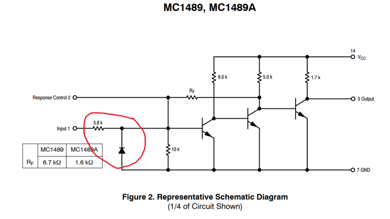
So what’s really required for an RS-232 (or EIA-232, if you’re under 50-ish) serial interface? The actual spec calls for at least +/- 3 V (up to +/- 25 V) for valid logic levels. So you’d think you would need a negative supply voltage to make this work, right? I mean, that’s why the Max232 had those capacitors, to run a charge pump to generate a negative voltage for the transmitter. That’s how you meet the spec. Well, it gets more interesting when you look at the common RS232 receivers that have been in use for several decades, going all the way back to the venerable 1488/1489 pair used way back in the days of TTL. A careful look at the circuit of the receiver shows that the very first thing on the input line was — a reverse biased diode to ground. That negative voltage was actually clamped, so anything less than about -0.7 V was a waste of electrons. There’s the specification, then there’s the common implementation and what will actually work.
With this knowledge, things get so much simpler. We don’t really need a negative voltage — at least, not for the vast majority of applications, meaning anything more modern than a Teletype terminal, really. If you’re not trying to run a serial line between buildings or in extremely high noise environments, a simple inverted data stream at, say, 3 or 5 Volts will do nicely.
I got tired of looking and hacked together something with minimum parts count (four parts), no critical component values, and low cost. Mine is well under a quarter. For two bits, it works great.
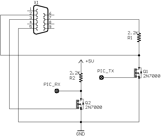
In the above circuit, Q1/R1 inverts the serial data from the source microcontroller (in my case, usually a PIC processor). I use the RTS signal from the remote end so that the voltage of the data send is very close to the voltage the other end expects to see. Using the local supply voltage (+5 or +3.3 V) will work just as well in every case I tried; it also lets you use only three wires (ground, TxD, and RxD) between devices. Q2/R2 inverts the serial data received from the remote device, and references it to the PIC’s ground and supply voltage. Although I show +5 V in the diagram, it could just as easily by 3.3V or whatever supply you’re using.
Why MOSFETs? Well, look at the advantages. No current limiting resistors for the gate (as you would need on a bipolar transistor base) — the MOSFET is a voltage operated device. The gate on a 2N7000 is rated for plus or minus 20 Volts, so you don’t need a clamping diode. They can be had DIRT cheap. I used to buy 2N7000’s from Mouser by the 2000-device ammo pack, bringing them down under a nickel each. For our European friends for whom sourcing 2N7000s can be a challenge, the BS170 is basically identical except for the pins being bass-ackwards. Now all that is needed is a drain limiting resistor, since the gate current is as close to zero as we are likely to care about. The value of that resistor is not critical in most applications; I found 4.7 K Ohms to be the best all around.
If your objective is to have a functioning serial interface that will exchange data with all or very nearly all RS-232/EIA-232 devices like PCs, laptops, and terminals, then this interface will do nicely. It’s the one I used for years in the ID-O-Matic and ID-O-Matic II kits, of which a few thousand were and still are in use around the world in ham radio repeaters and a bunch of other applications I never thought of when I designed them. I don’t recall more than one or two people who had any trouble at all with the serial interface… other than not being able to figure out how to make a serial interface work at all under Windows. I’ve also used it in several of my own projects, taking to a wide variety of devices with EIA-232 serial interfaces.
If your objective is to meet the actual EIA-232 specification, then yes — you’re going to need a negative voltage for your transmitted data. You could even get really picky, and only recognize incoming data as valid when it meets the actual specification (meaning, -3 to -25 V for a logic “1”). Of course then you wouldn’t be able to receive data from a huge number of devices.