The New Shack

I realized I haven’t posted anything since early this year when I struggling with equipment located upstairs and all of the RFI and other issues that caused. Since that time I’ve made a good deal of progress.

All of the radio equipment is now in the basement. It’s not idea as far as I’m concerned, but it is what it is. From a practical standpoint it makes sense. I can get coax straight out the back of the house, which makes grounding and antenna installation so much easier. It’s unfortunate that everything is crammed into a very small space. It’s a little built-in “nook” probably intended for study or something. A 51″ wide countertop, 24″ deep (if that); wall cabinets mounted above so it’s a little constrained both horizontally and vertically. A couple of duplex outlets, a phone jack – no Ethernet, and no way to get it there either. Doing any kind of wiring would require major demolition and construction. Just getting RG-8/U and a flat cable for the remote tuner control into that space took a lot, and I do mean a lot.

The antenna is now a 135′ (give or take a little) loop in a triangular shape around the back yard. The feed end is at about 16′; the two legs go out to two maple trees where the wire is up between 25 and 30 feet. Again, not ideal, but it’s what I could manage to get up in the air. A 1:1 balun at the feed point connects the antenna to 50′ of LMR-400, which connects to an LDG RT-11 remote tuner, and from there to the shack via about 35′ of RG-8/U.

I’ve successfully run 100W+ on SSB and CW with no interference with anything else, no RFI in the house, no issues with breakers. The RT-11 doesn’t match the antenna in all cases; on most bands I need to also use the TS-850’s internal tuner. Surprisingly enough, I’ve worked a couple dozen countries using 25 to 50 W on FT8, and one night worked a couple of Russians (grids LO02 and LO33) on 20 meter SSB. Log entries show that 40 meters is almost all US and a smattering of Canadians, with a few surprising exceptions – Japan, Spain, and France. I attribute those to guys in those countries with good beam antennas! Not surprisingly, the higher in frequency I go, the better the DX results are. I’ve even worked a few US stations on 80, but of course that’s pretty clearly NVIS so I don’t even try much.

I have the TS-850, SP-31, FT-817nd, the keyer, and a couple of Astron DC power supplies on the desk. I built a shelf for the SB-101 and SB-600/HP-23. On the other side of the desk is an SB-610 monitor scope I picked up, an HM-102 power/SWR meter, the control for the RT-11, and a coax switch to switch between the antenna and a dummy load.

I am planning a new shack, though. I’m slowly cleaning out my basement workshop and storage area. My plan is to revamp the storage area with nicer cabinets, and build a 6′ long operating desk about 30-32″ deep in one corner. A 4′ workbench will go next to that. I’ll have room for everything, and more room for a straight key and paddle in a more comfortable operating position. Right now things are a little cramped.

I’ve worked a lot more FT8 than I would like to admit, but I’ve also worked some SSB, one SSTV QSO, and even a PSK and an RTTY contact. RTTY and SSTV were firsts for me. None of those are confirmed; the RTTY and PSK contacts got lost in QSB but the SSTV was solid. I just wish I’d saved the darned image, I’m really bummed that I lost that. I blame the software.

Anyway… onward.

RFI from the shack, again, naturally

The other day I decided to try setting up the SB-101 and do some testing of the setup with the antenna tuner. As I tuned up with a few watts, things were OK… then I turned up the drive past 50 W, and things got wonky. The monitors on the PC flickered, the PC beeped, it logged me out, the CO monitor in the hallway beeped, and a few minutes later I noticed we’d lost our Internet connection. After a little investigation I found half a dozen GFCI/AFCI breakers in our main panel had tripped and had to be reset. It had dropped power to the entire kitchen, so the router was powered off.

Obviously there’s an RFI problem. I have all of the equipment grounded to a new copper bus bar using 12-18 inch flat copper braid, and the bus bar is grounded to the household AC ground. Ah, there’s the mistake. That puts any stray RFI onto the house electrical ground, which the breakers interpret as a grounding problem.

The shack is on the second floor for the time being, in the “spare” bedroom that has been my office for the past 15 years or so. I’m using a 71′ long end fed wire, with about 18′ or so of counterpoise. I’m feeding it through an MFJ tuner, but that means there’s a good deal of RF on the feedline inside the house before it snakes out through a window.

The eventual solution will be a remote auto tuner at or near the feedpoint of the antenna, outside and well away from the house. The interim solution? Limit my output to QRP levels. I can work some SSB with normal power, but CW or digital modes using much more than that is a recipe for electrical problems. It’s less than ideal, but once our new deck is built I should have a good mounting point for a remote tuner, and a feedpoint from which I can string up a full wave loop for 40 meters that should work pretty well on most other bands too.

The price of neglect…

Last summer I installed a mini-split heat pump on the garage. My goal was to make the garage usable as a work shop (and smoking lounge) year round, without sweltering heat in summer and frigid temperatures in winter. The summer thing worked out pretty well; the heat pump seemed to keep up and it didn’t impact the electric bill more than it was worth.

This winter was a little different story. I know the garage is a little leaky, but the unit seemed to struggle to keep it much above the low 50s on cold days, and my last electric bill was about double what we usually see. I was considering adding a supplemental heat source, and truthfully a little disappointed. The unit’s specs said it would operate down to something like -4 F.

Yesterday afternoon I wanted to make a change to the aiming of the air vent, and noticed that there was barely any air flow. What little there was was quite warm, but it was obviously not enough to do much good. Hmmm. I grabbed a ladder and checked the intake filter on top of the unit… and found it almost totally blocked by a thick layer of brown crud.

Dummy!! After all the time I spend trying to get our rental tenants to change their furnace filters, I let this happen! And I should have known it would clog up, as I spent hours running the table saw out here to make cabinets and stuff. I rather sheepishly vacuumed the screen off and plopped the filter back in place and was rewarded with a blast of warm air that fairly quickly brought the garage up to the set temperature.

Lesson learned! I’ll be cleaning that at least monthly, and replacing the ERV filter on schedule. Things don’t work right when you don’t take care of them. I knew that and still got lazy and neglected it. That won’t happen again.

New fenders scored!

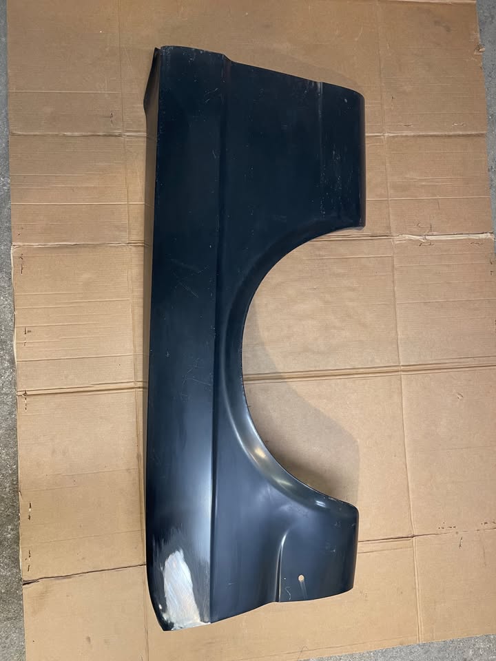
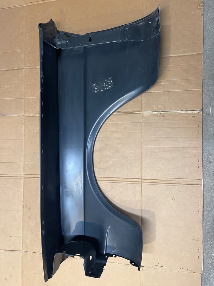
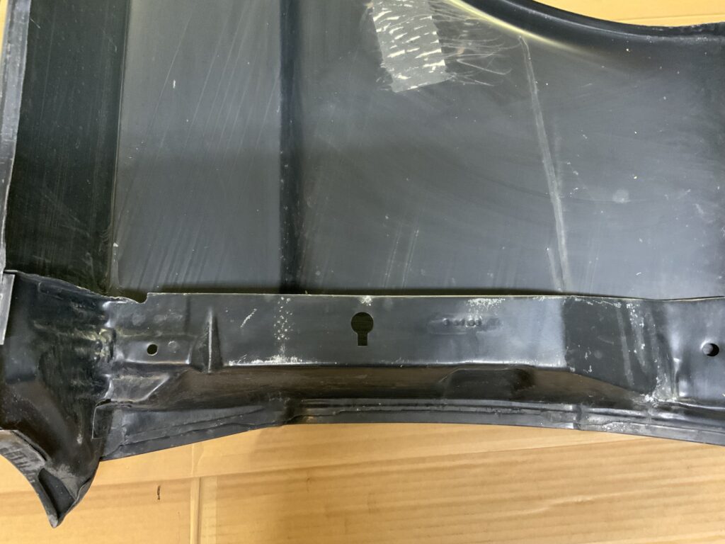
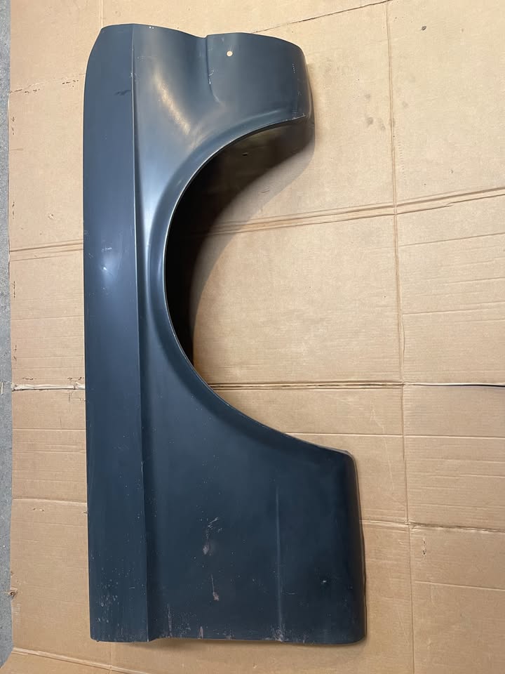
I found a pair of “new”, as in new old stock, fenders for the Mustang listed on Facebook Marketplace. After a little digging, these appear to be manufactured by Ford as service replacement parts. Lord only knows when. They’re not 1960s vintage, as those were primed in red with the part number stenciled on yellow in the inside. These are black primed, and they had parts system stickers on them at some point that were scraped off. So I have no idea when they were produced, but the date stamps indicate they were Ford parts. They seem to be pretty decent quality, a little heavier gauge steel than I have seen on some new parts.

The old fenders are too far gone to save, and I got these for less than a single new repro part would cost me after shipping. In fact, maybe less than one before shipping. NPD carries two different brands of fenders; one is under $250 and the other over $450 per side. Plus truck freight, of course. Are the cheap ones decent? Can you tell the difference between those and the expensive ones? Don’t know, and no real way to tell. Reviews aren’t terribly helpful; one guy’s “These suck” may be another’s “The guys at the restoration shop were able to make them fit with a few hours’ work”. Whatever, now I don’t have to worry about what to buy.

SB-101 Dial Drive Overhaul

When I bought the Heathkit SB-101, the dial drive was a mess. The dial itself, of course, was old and severely cracked. Much worse, though, was that FedEx had dropped the rig on its face – and even though it was bubble wrapped, whoever packed it didn’t bother to put Styrofoam blocks between the knobs. That would have protected the face and knobs, but as it was the main tuning dial was damaged. The aluminum skirt was bent, and the drive pulley was damaged.

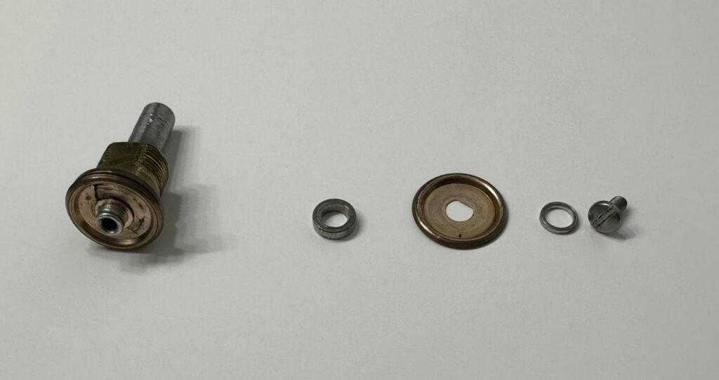
The drive pulley consists of a pair of bronze washers, each with a rolled bead near the outer perimeter, which are spaced slightly apart using a tiny aluminum spacer. That assembly grips an aluminum drive ring that’s attached to the plastic dial. The raised beads put pressure on the drive ring to turn the main dial. Well, on mine, one of those bronze washers is cracked and bent. I was unable to get it sufficiently straightened out to give a solid grip on the tuning drive ring all the way around, so the knob would slip on the dial. Of course no replacement parts are available anywhere, other than from a parts rig – which I don’t have.

With nothing to lose, I decided to try something new. I got the damaged washer as straight as I could, then grabbed a 2 x 5 mm silicone O-ring left over from a coffee machine repair. I put that around the spacer in between the bronze washers and reassembled the mechanism. Success! The operation was now smooth, positive, and free of the slippage I’d experienced before.

Left to right: The shaft and outer drive washer, crack visible at about 11 o’clock. Next is the middle spacer, inner washer, end spacer, and the screw that holds it all together.

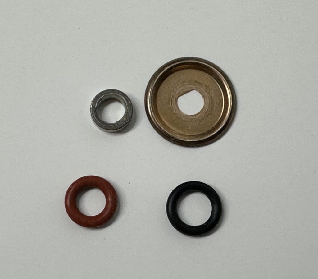
After a few days of use, however, I noticed some slipping again. I suspected there was a little oil or grease that had migrated to the O-ring, and I was right. I pulled the assembly apart and thoroughly cleaned everything with some 91% isopropyl alcohol and paper towel. When I re-assembled it, I used a #009 neoprene O-ring. It’s very close to the 5 x 2 mm O-ring I had in there before, but I was hoping that the very slightly smaller cross section and the neoprene material might give a little more traction. I also used a Q-tip with a little alcohol to clean off the dial drive ring, in case there was oil or aluminum oxide on that.

The middle spacer and inner washer, with the silicone (red) and neoprene (black) O-rings.

With everything back together, I once again had smooth, positive drive with no slipping. Time will tell how well this fix holds up, but it’s definitely better than the nearly unusable state in which I received the rig.

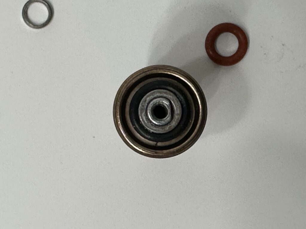
The new O-ring in place around the center spacer before re-assembly

So far the tuning dial has worked out OK. If it fails, I have a vague plan for a 3D printed center hub for the dial with a ring gear, and a pinion gear for the dial shaft. I understand why this might be one reason the HW-100 is more popular than the SB-100/101/102, but this may also help some owners of other SB-line gear like the SB-300/302 and 400/401.

SB-101 Troubleshooting, Part 3

After getting some really good advice from the Heathkit Radios group, I did some further troubleshooting. I re-soldered much of the RF driver board, having found a spot that would change the symptoms when it was hit with freeze spray or tapped with a wooden probe.

At one point, I just got curious as to what the SSB performance was like compared to CW. Surprise! In SSB mode, I could key the mic and get pretty good output. That told me the problem was limited to CW and tune mode, which pointed only one place… the mode switch! I had cleaned that switch at least once before, but I did it again. A squirt of the nearly depleted can of Radio Shack tuner cleaner, a dozen or more rotations in each direction, and … yes, now it’s working.

After completing the transmitter alignment procedure, I put the whole thing back together (mistake, as it turned out) and took it all upstairs where I have my other rigs. I tuned the TS-850S to WWV and zero-beat the 100 kHz calibrator as closely as I could. Then I figured out that i really needed to move the dial pointer on the LMO shaft. Remember how I said I’d put everything together? It’s a real bear trying to get at the set screw to make that adjustment when it’s in the cabinet. I managed, but I may have used a word that I would not repeat on the air.

With all that done, I resorted to a sked and had a nice chat on 20 meters with Dan, W7RF. I was tuned up for close to max output, and got a good report for audio and signal strength given my little 70′ wire in the trees in the back yard. The rig is now officially “in use”!

SB-101 Troubleshooting, Pt. 2

The previous work got me thinking. The LMO problem was, apparently, flaky rivets at the RCA connector; I peened those and the instability went away completely. The scratchy noise in the audio was fixed by generous application of desoldering braid and fresh solder on the audio board. And, whereas I was seeing only a few mV of RF at the output side of T1 (the balanced modulator output transformer), after again re-soldering a few points I’ve suddenly got close to the expected level – about 260 mV peak. No real explanation for why it suddenly jumped from 25 to over 250 mV. All of this points to bad connections and oxidization.

Now onward. V3 is not amplifying as it should. I get about 150-175 mV peak RF out of pin 5 (the plate) where it should be around 7 V. I swapped V3 with V4, then V2 & V3 with V10 & V11, since they are all the same 6AU6 type. Of course that didn’t make a difference. I’m not expecting to find bad tubes. What I suspect is happening is that there is old flux contaminating a number of solder joints. After sitting idle for decades, there is now oxidization that is getting disturbed by heat and motion. That’s causing these marginal or bad solder joints to rather randomly manifest themselves. The solder joints all look OK; most are not terribly pretty, as I would expect with a Heathkit, but solid. It’s telling, though, that de- and re-soldering is fixing so many issues. I decided to simply go through and de-solder, thoroughly clean, and properly re-solder every joint I could get to on the IF, bandpass, and driver boards.

I also had a very flaky meter zero potentiometer, and if it’s bad then the carrier null is probably not far behind. Of course you can’t buy direct replacements for the originals, so I bought some new top-adjust 10 turn trim pots. One of them fixed the meter zero issue quite nicely, and I’ll replace the carrier null pot when I have time.

Unfortunately none of the work I have done has had the slightest impact on the RF output. It’s still next to nothing. About 1W or less on 80 meters, and maybe 10 or 12 on 10 meters. I’ve asked advice on the Heathkit radios group (here) and and working with a couple of guys who understand tube circuits better than I do to troubleshoot.

SB-101 Troubleshooting

Wow, what fun we’re having!

This rig has been one problem after another. After I got all of the bad resistors replaced, a new problem occurred. No or close to no RF output. I can coax a watt or so out of it on 80 meters, maybe 5 W out on 10 meters. My troubleshooting efforts were hampered by the fact that while I could probe around all I wanted with an O-scope or meter, nothing in the manual gave any indication (at least none that I could find) of the expected RF signal levels in the path – the carrier oscillator, VFO, etc. So I could see the carrier oscillator was producing about small fraction of a volt peak to peak, but I had no idea if that was right or not (but it seemed awfully low to me).

Here’s where the folks in the Heathkit group at groups.io really were helpful. It turns out that the schematics printed in the manual for the Heathkit HW-101, which is nearly identical to the SB-101, do indeed show expected RF signal levels at numerous points in the circuit. Armed with that information, I confirmed that at least part of the problem was a very low signal from the carrier oscillator. In an effort to double-check my work, I went back and re-checked every part I had replaced – after which the oscillator signal was fine (more or less). That told me there was a physical problem. It could be bad solder joints, bad ground, a cracked board, or a cracked part. Just poking around with the meter probes had changed things.

After much trial, tribulation and scope work, I spent some time de-soldering and re-soldering most of the modulator circuit board. That seemed to stabilize the carrier oscillator in a working state. I had to do the same to the audio board to solve a newly developed scratchy intermittent noise issue that appeared. Along the way I discovered a bad connection to the LMO output RCA plug. Then the LMO started randomly jumping 1, 2, or maybe 10 kHz whenever it was tapped or touched. I ended up peening the two pop rivets holding the phono jack in the back of the LMO to fix that one.

Now at least I’m back to having a relatively stable, quiet rig with a fixed symptom I can chase. That symptom is a good signal from the carrier oscillator reaching the balanced modulator, a relatively normal signal at the input to the modulator transformer, and not much of anything coming out of that transformer. Right now I’m feeling a little foolish because I had that transformer out of the radio this morning, opened it up, re-glued the coil form to the base, checked that the wires were still attached to the pins… and did not check the windings for continuity. What a rookie move. I’ll check that in the morning.

SB-600 Speaker

Unfortunately, I discovered that the speaker coil of the SB-600 is open and the speaker is dead. The SB-600 is a station speaker that matches the SB-101 and holds a singe 8 Ohm, 6” x 9” speaker. The radio’s HP-23 power supply also mounts in the cabinet behind the speaker. After tearing it down I found that the wire between the connection terminal and the coil itself was broken – this is where a very fine wire is stuck down to the paper cone with some sort of enamel or lacquer coating. I don’t feel bad about trashing the speaker to find that out. Even if I’d been able to find it right away, I don’t think I’d have had any success trying to expose the wire and solder it back together on top of the very brittle old paper cone. Better to just replace the speaker and hope the judges don’t notice and deduct too many points at the Pebble Beach Concours d’Elegance for ham radio equipment.

6 x 9 speakers are pretty common, mostly used for car audio. Unfortunately most are 4 Ohm impedance, are not sold singly, and are pretty expensive for this application. While cheap, paper cone 8 Ohm speakers were very common fifty years ago, they aren’t now. I do have a couple of 4 Ohm car door speakers, but they’re the wrong size – 4″ x 6″. I tried one and it seemed to work fine on the SB-101, so I went ahead and ordered a new low-end single 6×9 replacement speaker rather than spend weeks trying to source an 8 Ohm speaker at a reasonable price. Ah, the best laid plans…

I wanted to freshen up the paint on this and the SB-101. They’re not in bad shape, but after this much time has passed since they were new the cabinets collect some nicks and scrapes. A fresh coat of paint is not out of line. Will, N5OLA also sells color-matched paint for the Heathkit SB and HW series equipment. He’s got both spray cans and bottles of touch-up paint with brushes in the caps. I ordered a can of each. Of course the spray paint isn’t textured like the original, but I’m not stripping down to bare metal – just spraying a light coat over the existing paint. I figured if it were too glossy I’d “dust” on a couple light coats to knock down the sheen and preserve the original look. I need not have worried; the paint is a perfect match in both color and sheen.

With the paint done, all that remained was to get it all put back together with the new speaker and the power supply mounted in the back. The HW-series paint is a darker, more turquoise green that is a nice match for the speaker grille on the SB-600. I mainly bought that paint to see if it’s the right color to turn my HG-10 VFO into an HG-10B so it matches my HW-16 transceiver (it is and it did), but it matches the SB-600 grille so well I went ahead and shot a coat on that as well. That takes care of the places where the four black screws for the speaker had taken the paint off when they were installed.

Naturally the speaker mounting holes were off a little, and it was just a touch too wide in the 6″ direction to fit the cabinet. A few whacks with a ball-peen hammer to flatten the sheet metal edges took care of the size, and a step drill bit enlarged the holes enough for everything to fit right. Unfortunately, the audio output is too low and distorted for this to work on its own. I ordered some 4 Ohm 10 W resistors. Adding one of those in series with the speaker made things better. Not perfect, but better. If I find a suitable 8 Ohm speaker for a reasonable price, I’m going to replace it (even though that means pulling the HP-23 back out again, which I don’t enjoy).

I had ordered some new replacements for the rubber feet that Heathkit used – sold as “cutting board feet” on Amazon in several different sizes. With the power supply mounted and everything back together, it looks just great. I’m glad I took the time to shoot a fresh coat of paint on it. I even taped off the Heathkit sticker with the model and serial number.

SB-101 component replacement

Based on N5OLA‘s excellent diagrams, I went through the SB-101 last week and checked all of the resistors I could get to. I found a dozen or so that were well out of tolerance and ordered replacements from Digikey. I’d have used what I have on hand, but all of my resistors are 1/4 W or 1/8 W. I think all of the carbon comp resistors in the Heathkit are 1/2 W, so I ordered new metal film 1/2 W 2% replacements. They’re much smaller than the old resistors.

Yesterday and this morning I de-soldered and replaced the out of tolerance resistors. I also installed a “re-cap” kit from Hayseed Hamfest to replace a lot of the capacitors in the rig – all of the electrolytics, and many of the tubular paper and resin capacitors. I didn’t get all of them replaced, as a couple are just a lot of trouble to try and get out. The resin caps I pulled were all testing right at where they should be, though I don’t really have a convenient way to test leakage or ESR. With the part replacement done, I crossed my fingers and fired the rig back up. At first I thought I had no audio – there was no sound from the speaker at all. I turned the function switch to CAL to find the calibrator signal and see if the RF section was working – and heard the cal signal in the speaker! The audio section isn’t dead, the receiver is just way, way quieter than it was before. The slight hum that was present before is completely gone, and the receiver seems a lot quieter. I tuned around, and from my basement with nothing more than about 3 feet of wire draped over the end of the workbench was able to find the FT8 circus on 40 and 20, and a couple sideband and one AM QSO on 40 meters. I’m pretty stoked at this point. I’m hoping the cabinet paint from N5OLA arrives soon; I want to get the SB-600 put back together with the new speaker and the power supply re-mounted, then drag it all up to the shack and get the calibrator zero-beat with WWV. I have a little 90s-vintage Radio Shack frequency counter, but it’s nowhere near good enough to nail that 100 kHz crystal oscillator down to the last tenth of a Hz or less. And don’t think for one minute that I’m not once again tempted to pick up a “real” frequency counter and maybe an RF generator from eBay…