
Note: edited 7/28/25 and image updated 2/27/26; I refined this by removing one diode and dropping the supply voltage a bit. The updated schematic below reflects that change.
A few days ago, I replaced the dim and occasionally flickering CFL backlight from my TS-850 with a length of LED strip light. At first I was pretty happy with it – until the first time I tried to transmit, that is.
To recap, I ran power from the power switch white lead (switched input DC voltage) as I had seen in a couple of Internet posts. I ran that through a total of four 1N4001 diodes in series. The 13.8 V supply voltage really drove the LEDs too bright, and two diodes provided enough voltage drop to make it more reasonable — though as I used it, it became apparent that it really could have used another series diode. The second pair of diodes were bypassed by the display dimmer switch. All well and good; it seemed to work fine.
Then I connected a new power supply thoughtfully provided by a friend (thanks, Dan!), connected a dummy load, and went about setting up the rig for use and testing the power supply’s performance. I set the supply voltage at 13.75 V, and as soon as I started transmitting into the dummy load I noticed that the display would dim quite a bit. In fact, if I set the dimmer switch on (display dimmed) and transmitted, the display would blank entirely. Not good!! It turns out that the white wire on the power switch – well, I don’t know what all is between it and the input; the schematics in the TS-850 service manual are almost impenetrable. Wherever it’s coming from, that line will sag down to 11 V or even lower when the rig is transmitting. It’s totally unregulated. Obviously I needed a better solution.
It occurred to me that, since I’d replaced the capacitors on the display board, maybe the original backlight would be OK. I re-installed the tube and re-connected the inverter and fired up the transceiver – but the display was still pretty dim. After seeing it nice and brightly lit by the LEDs, I wasn’t about to go back to squinting at that. The serial number on my rig indicates it was manufactured in December of 1993; I guess thirty-odd years is a bit of a long time to expect a CCFL backlight to stay healthy. I spent a little time looking for a suitable replacement tube, but aside from not finding one with the right length, I have no idea what voltage is being produced by the inverter – and I’m really not in the mood to screw with it.
After some pondering, I settled on a new approach. I ordered some DC-DC boost converters from our favorite purveyor of just about everything (Amazon). These will take a wide range of input voltage – 2 to 24 V claimed – and convert it to a higher output voltage – 5 to 28 V they say. All I need is to bump the regulated 8 V power up to around 12 V to drive the LED strip. I can adjust the output to get the brightness I like, then switch in the diodes to drop it a little for the dim display setting. These boost converters cost well under a buck each, so I’ll keep a couple around just in case they don’t last as long as I do. I’ll make sure to bag one or two up, along with a replacement LED strip, to go with the transceiver when I (or my heirs) sell it. I’m not going to bother posting a link to the Amazon item because I’m sure in six months it will be a dead link. Just search for “DC-DC step up converter” or similar and sort through until you find a suitable model for you. You could also design one from scratch for extra ham credit.
I designed the circuit below to be as flexible as possible. You don’t need to modify the dimmer switch board; it remains entirely untouched. No soldering to the power switch. All of the wiring is completely on the display board. I happened to have a couple of small SPDT relays with 12 V DC coils on hand, but designed it so that you could use much any relay that has a normally-closed contact (so, SPST-NC or SPDT). These relays can be had dirt cheap. The coil voltage just needs to be 12 V give or take a little; nothing in this whole exercise needs to handle more than maybe 130-150 mA.
About the only inconvenience I ran into is that the DIM switch circuit doesn’t go directly to the CCFL inverter connector, so you’ve got to solder a wire to one of the ribbon cable connector pins. Not a huge deal. No major modifications to the display board are needed, but you will need to cut the small trace that runs from Pin 2 of CN1 (the display dim signal) to one of the SMT resistors in the board. That circuit feeds a PWM driver chip, and the circuitry there will prevent the relay from releasing once it’s turned on. That means that if you dim the display without first cutting the trace, you won’t be able to un-dim it until you turn the rig off. So, a minute with an X-Acto knife does the job.
In this circuit, the 8 V supply is picked off of the original inverter input connector and fed to the DC-DC converter. Adjust the output of the converter for 12 V or give or take a bit, whatever level gives an appropriate brightness for the LED backlight. The output of the boost converter is connected to the relay coil as well as the relay’s NC contact. The other side of the relay coil is connected to the DIM switch input from the front panel, which is grounded to dim the display and otherwise floats.
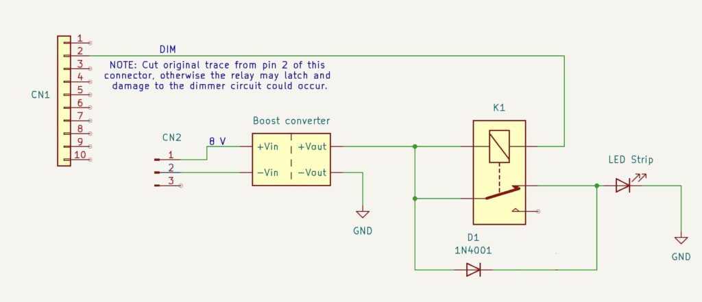
With the display switch set for full brightness, the relay coil is not grounded and the relay is not energized. Current flows from the DC-DC converter to the LED backlight through the NC contact of the relay, bypassing the diode.
With the switch set to the DIM position (pushed in), the switch grounds one side of the relay coil and energizes the relay. Current now reaches the LED strip through the diode, which provide enough voltage drop to dim the display. Diode choice is not terribly important and can be changed to suit your individual preference for the difference between full brightness and “dim”. You could add a second diode in series if needed. My LED strip draws around 130 mA at full brightness; a 1N4148 would probably do the job as well. I just didn’t happen to have any on hand, which is strange given the thousands and thousands I’ve bought over the years for various kits I sold.
Installation is pretty straightforward. I removed the CCFL tube and slid the adhesive-backed LED strip behind the LCD, then used a piece of tubing I happened to have on the bench to reach through and make sure it was securely stuck down all the way through. A piece of dowel would be good too. I removed the inverter and its connectors entirely – no sense leaving that there with the tube gone. I used CN3, the inverter supply connector, for the ground and 8 V inputs to the boost converter. I soldered the diode assembly directly to the relay, then used some hot-melt glue to stick the relay to the board. The DC-DC converter then mounts onto the relay with more hot-melt glue – just be careful to keep anything from shorting. There’s enough room to sandwich a little spacer of balsa or plastic or something in there if needed. The converter I used has an adjusting pot that I made sure was facing upward, so I could adjust it from the top.
I left the LED strip disconnected during the initial power-on “smoke test”. I had no idea what voltage the little board would be putting out. It turned out to be 18 V. I adjusted that down to 12 V and powered the rig off. Then I soldered the LED wires in place and powered on again. I tested the dim function and found it to be too dim on that setting, so I tweaked the voltage a bit to give me a good display on both settings. This will depend on your particular LED strip, but in my case I ended up with the output of the DC-DC converter set to 13.3 V. My first iteration of this used two 1N4001 diodes in series; I later switched to using a single diode and reduced the supply voltage to 11.5 V. That gave me about 10.75 on the dim setting, and the display looks great either way.
Now, why so complicated with the relay? Can’t you just use the dimmer switch directly without the relay? Well… sort of. Unfortunately, the way that switch is connected on the little switch daughter board, isolating the pins to use for this is a challenge. I ended up having to de-solder it from the board, cut off a couple of leads, and re-solder it. It’s too much surgery and is irreversible. I ended up buying a replacement from eBay; fortunately, it was relatively cheap, but obviously no new ones are being made, and I wanted to present a solution that involved as little butchering as possible.
Since this is a modification that may confuse someone encountering it for the first time, my plan is to pack up the schematic, a spare boost converter or two, and a spare chunk of LED strip and keep it with the rig. Some day someone else will probably own this transceiver, and they may appreciate not needing to reverse engineer all of it.
And finally, yes, I did see the packaged solutions available from a couple of places. Both are coming from outside the US, with all of the delay and shipping expense (and uncertainty) that comes with it. They’re also pretty spendy. I figure I’ll have under $2 worth of parts wrapped up in this project, and a left-over pile of little DC-DC converters and several feet of LED light strip that will probably soon adorn my 3D printer or something.