
With the display fixed, I set out to do some alignment and adjustment on the TS-850. One thing I encountered was an issue with the attenuator. The 850 has two front panel buttons to switch in 6 and 12 dB attenuators, or both for 18 dB. One thing I had noticed was that the 6 dB attenuator seemed to work, but any time the 12 dB attenuator was switched in it completely killed the signal. Looking at the schematic, the only thing I could spot as a cause for that would be resistor R3 being open. I decided to pull the RF board and investigate.
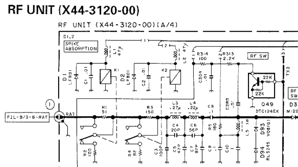
With both attenuators off, relays K1 and K2 are both actuated. The signal from the antenna passes through K1 and K2, bypassing resistors R1 and R3. When the 6 dB attenuator is switched on, K1 de-energizes and puts a 6 dB resistive divider (R1/R2) in the signal path. The same method is used for the 12 dB attenuator (R3/4), activated by dropping relay K2.
Once I got the RF board out, the bottom of the board plainly showed that I was not the first one here. Portions of the board underneath the attenuator section were scorched, some SMT resistors were missing, and a 1/4 W resistor was soldered in place of R1. There were signs that some other components were damaged as well. I unsoldered and removed the “rework” resistor and found it to be the wrong value. Oddly, the board doesn’t match the diagrams I found in the service manual I found on line — a couple of the resistors have been replaced with pairs of resistors in parallel. That added some additional challenge to the process as I figured out the changes.
Eventually I found that something had damaged both R1 and R3. I found 1/8 W resistors of the correct values (51 and 150 Ohms – I had 50 and 150, close enough) in my parts stock. With those soldered in place of the defective SMT parts, I put it all back together and powered the rig back up, and got… nothing. Static. My little Elecraft XG2 signal generator was pushing 50 mV into the antenna jack, and the rig couldn’t hear a thing. I fed the signal directly to L3 and was able to hear it – weakly. So, back out comes the RF board.
Some probing with the DMM found a near dead short (1.4 Ohms) from the tail end of the attenuator at K2 to ground. Obviously that was a problem. Eventually I found capacitor C3, a little 100 pF SMT part, shorted. I removed it from the board and re-tested – now I can clearly hear the signal from the XG2, AND both the 6 and 12 dB attenuators work as they should. I don’t have a replacement for C3, but it’s part of a low-pass filter that I’m not terribly worried about right at the moment. I’ll pick up a 100 pF cap and replace it at my next opportunity. I also don’t know why it failed in the middle of a repair. It obviously wasn’t shorted before I started troubleshooting this issue, as I was able to receive signals off the air. All I can figure is that maybe it was physically damaged but not completely failed, and the probing or heat from the nearby soldering iron did it in. No matter – capacitors are cheap.
Now, on to the next issue — the S meter. It doesn’t “S”. Even with a 50 mV signal, there’s no reading on the meter; I’ll have to go through the alignment steps again to see if I can figure that out. Unfortunately that part of the procedure calls for a more capable signal generator than what I have. I should be able to get in the ballpark with the XG2. The service manual calls for 6 dB and 32 dB – or 1 uV and 40 uV. The XG2 will generate signals on 80, 40, and 20 meters at 1 or 50 uV. I should be able to set the S meter to read pretty close, assuming I don’t run into some OTHER issue that requires ripping the radio apart again.