One reason some people go for the HW-101 over the SB-101/102 is the SB series’ rather more complicated tuning dial indicator. It’s a pretty involved mechanism. The main tuning knob turns a little pinch wheel, which drives a small diameter aluminum ring attached to the 100 kHz acrylic main tuning dial. Kind of a simpler (no doubt cheaper at the time) reduction drive than using a Vernier. I think the reduction is about 8:1, give or take.
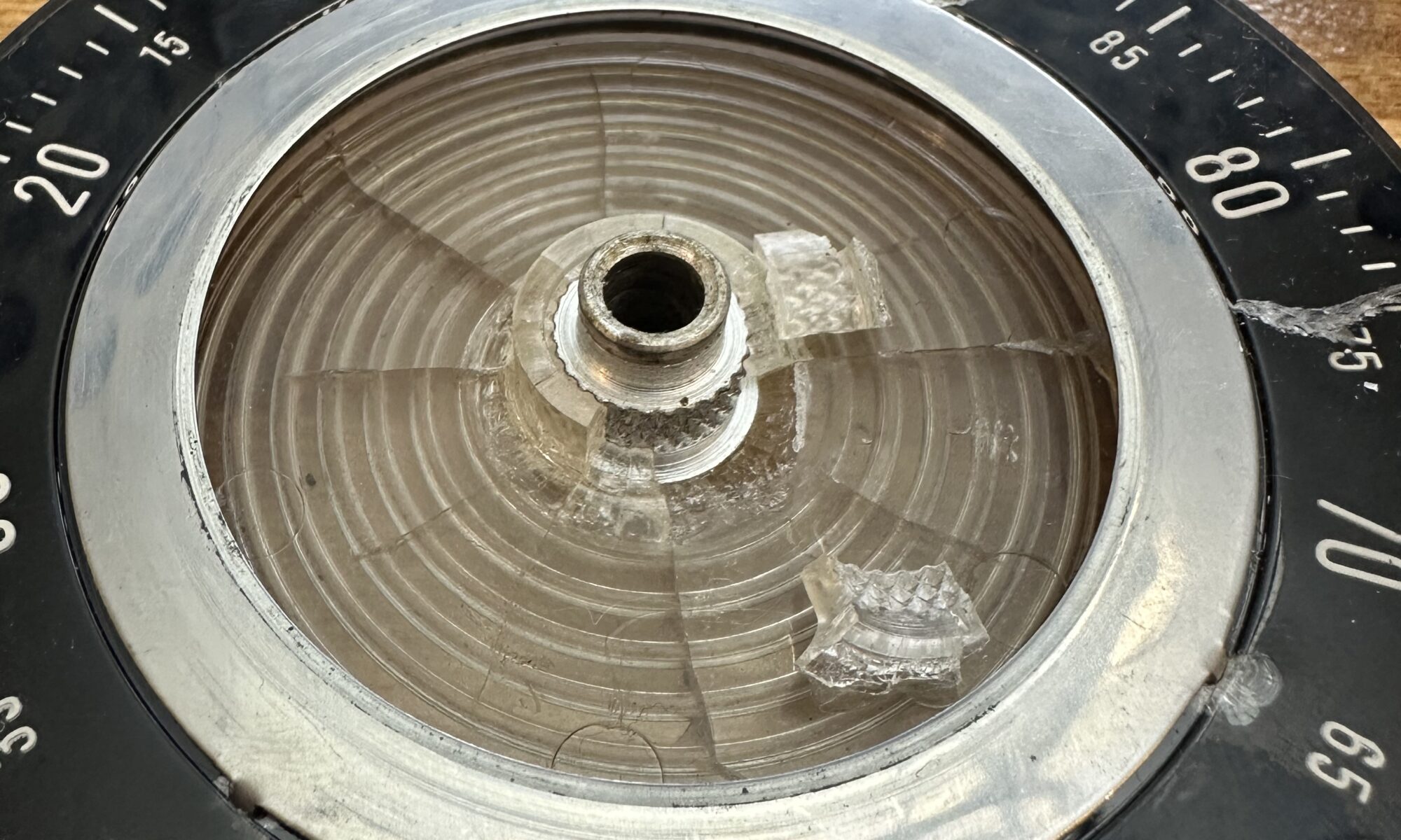
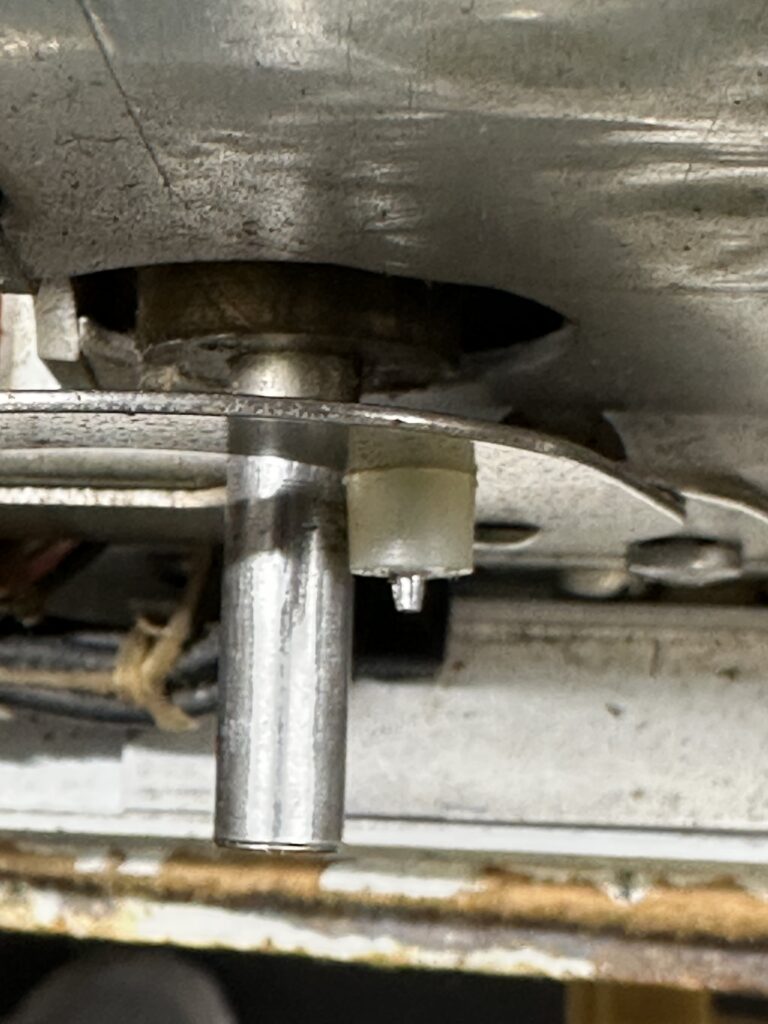
On the back of the main tuning dial is a spiral groove. There is a sliding pointer above the main dial that indicates the 100 kHz segment you’re in. So, each revolution of the main dial moves the pointer by one division, so you get pretty good resolution across 500 kHz of the band. That pointer is moved by a pivoting arm with a little nylon follower, a tiny nylon pin that rides in the spiral groove of the main indicator dial.
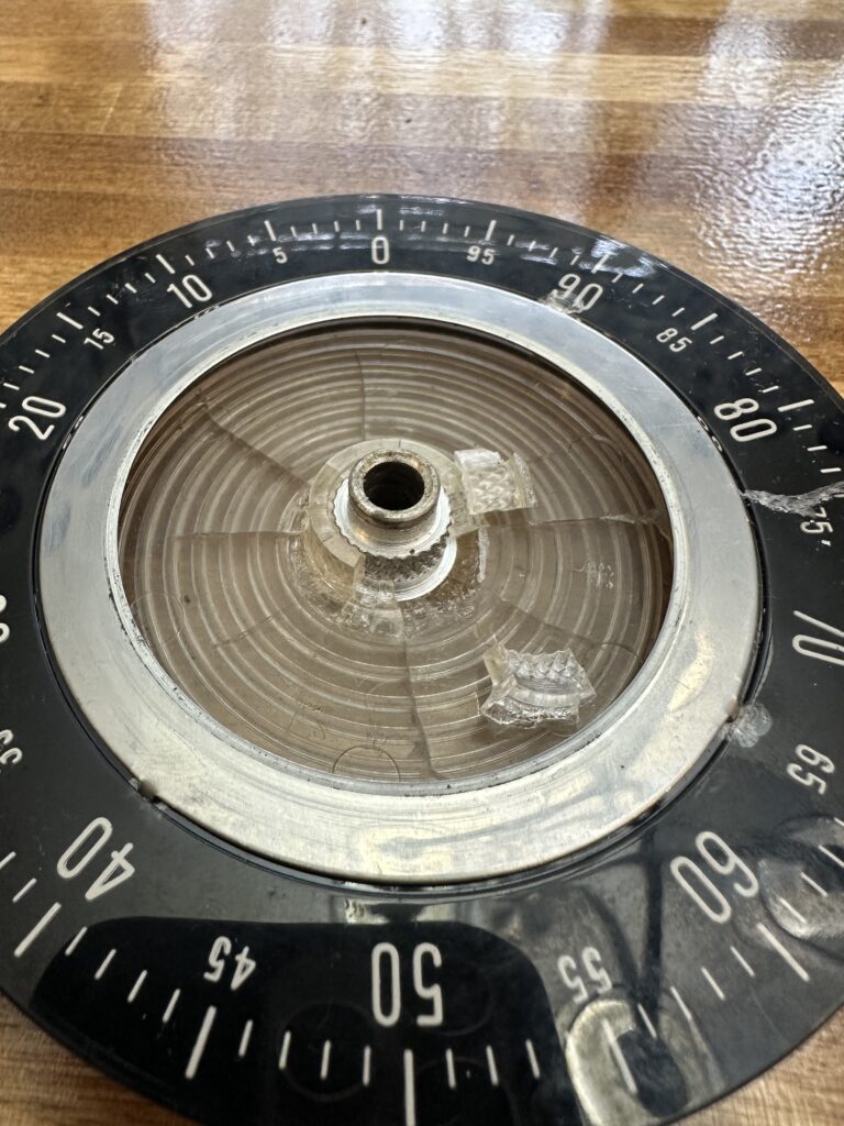

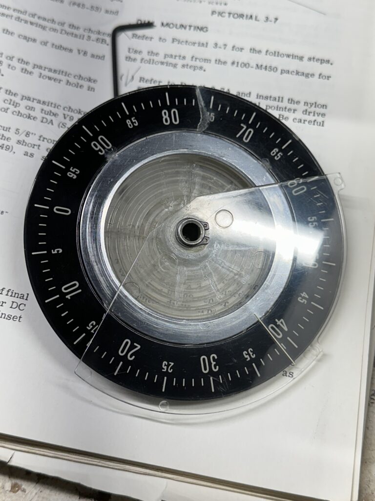
As you can see, the main dial has quite a bit of cracking radiating from the aluminum hub. One of the cracks goes all the way to the edge, running through approximately the 75 marking. The rest are more limited, but cracks never sleep. Also, the pin on the follower for the sliding pointer is broken off. So, there are two major problems to address. The minor issues include a bent skirt on the main tuning knob, and a bent pinch wheel for the tuning dial.
Of course none of these parts are in production any longer, and no new reproductions are being made either. I haven’t seen any for sale on eBay. The only source of parts, I suppose, would be other radios in the series to part out – and hope that they’re better, not worse. Rather than try to scrounge replacements, I decided to repair what I have. If I’m successful, the only thing I don’t think I can really fix is the cosmetic crack through the dial. If I get everything working, and mechanically sound enough to remain working, I can live with that. At some point I guess a new overlay could be made for the tuning dial, since it’s opaque. There are pilot lamps on either side to illuminate the dial, but it’s not backlit.
I began by getting everything taken apart and taking some measurements. The spiral groove seems to be around .060 or so; a .050 pin rides perfectly in it. After taking stock of what I have around and doing a little web research, I decided to try fabricating a new pin. I ended up chucking an M2 metric screw in a drill (a stack of nuts lets the drill chuck grip it) and turn it while filing the tip in a sort of ghetto lathe kind of arrangement. A little bench metal lathe would really have come in handy here. I’d have preferred to just fabricate the whole thing out of Delrin or something. Anyway, turned it down to around .050 – .055 until it was a smooth fit in the groove, and smoothed the pin as best I could. I drilled a slightly undersized hole through the nylon bit and secured the whole thing to the pivot arm with the pin sticking through the nylon. Honestly it would have been a lot easier to just use a few washers and a nut on the screw.

I used some water-thin acrylic glue and brushed it on each of the cracks, front and back, to try to seal them us as well as I can. I used Tamiya model glue but there are other brands that would work well. Not CA glue, actual solvent model glue. Anyway, I also glued the broken hub pieces back in place and clamped them while they dried, just for mote support and stability. Gluing the big crack left a mess on the front of the dial, so I used Micromesh pads followed by Novus plastic polish to clean that up and leave the dial face smooth and polished. I also used Novus on the fan-shaped index line piece, as it was pretty well scuffed. It’s not perfect, but I think it looks pretty good for a 50-plus year old piece of plastic.
Now on to reassembly…