Better late than never! While I wait for the new 80 M crystal to arrive, I made use of Will, N5OLA’s excellent information to do a quick check of the resistors in the rig. Will has some incredibly nice and useful videos on YouTube detailing his process for restoring and repairing Heathkit SB and HW line radios, and has been very kind and helpful in sharing information. He’s even supplying me with a replacement for the broken oscillator coil plaguing the 28.5 & 29 MHz bands on this transceiver.
I was looking for badly out-of-spec carbon composition resistors. When they drift, they always drift “upward” – meaning, higher resistance. My strategy is to check them in-circuit. A lower reading than spec is fine, it just means I’m reading the resistance of other parts of the circuit. A higher-than-spec reading must mean that the resistor has a higher resistance than it should. Anything at 15% or beyond gets replaced. For example, a 47K Ohm resistor that reads 51.7K is fine; it’s within spec even when new. If it hits 54K Ohms, though, it’s getting replaced. I realize that this approach may result in out of tolerance resistors being left in place – but I’ll chase those down if and as problems occur. The alternative is treating every resistor in the rig like a dog – lifting one leg to check the value. Yeah, I just made that up. Sorry.
I found a dozen or so resistors out of tolerance and put an order in at Digikey for those, as well as a couple of other small parts. I also ordered a re-cap kit to replace electrolytic and mylar capacitors that don’t age well. Hayseed Hamfest sells a nice little kit with the caps needed, and they’re no more expensive than ordering the individual parts from Digikey. I’ll give a ham the business.
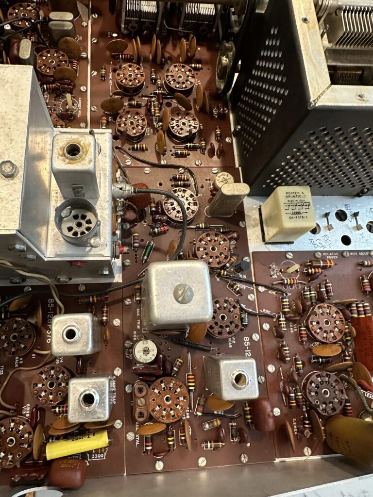
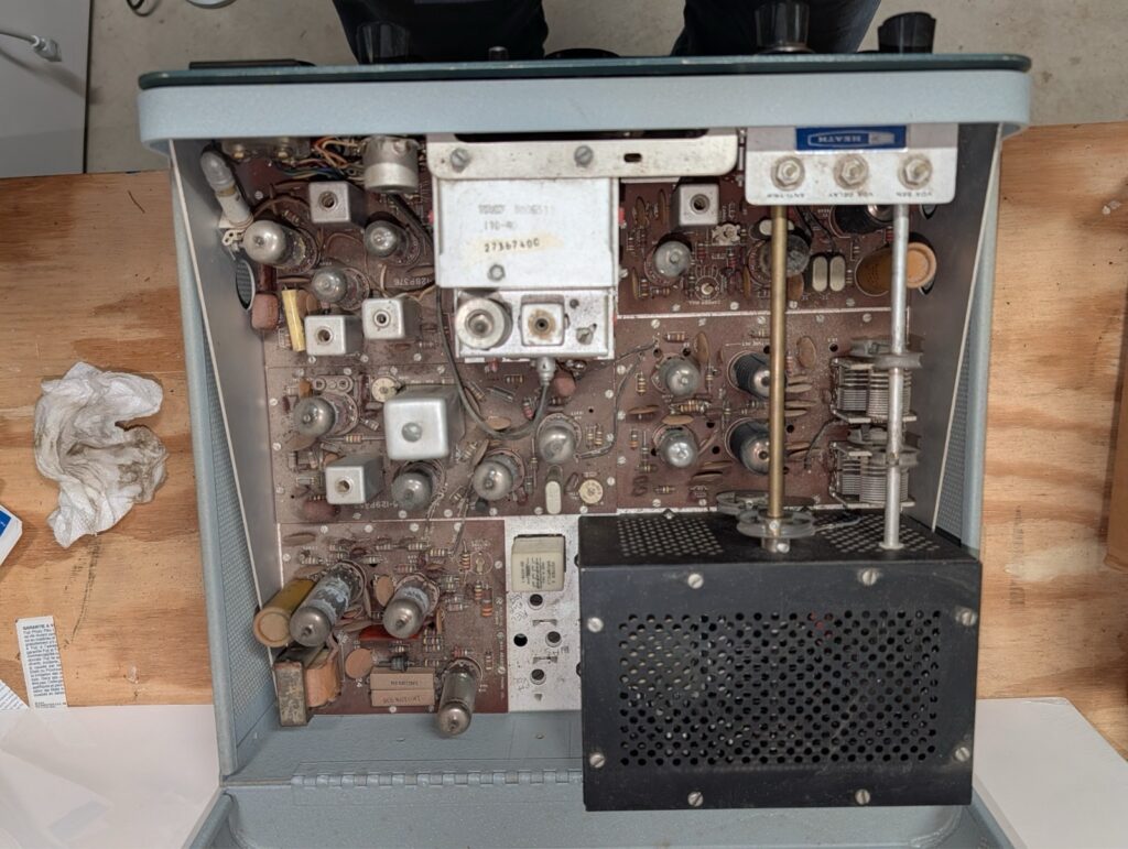
So I’m waiting for a crystal, some resistors, a coil, and a bag of capacitors. Rather than chase down problems that those parts will or might fix, I decided it was time for a bath. I removed all of the tubes and tagged them with their locations using masking tape on the side of each tube. Then I gave the top side of the circuit boards a liberal spray of Dawn Powerwash and gently scrubbed everything I could with a small paintbrush and an acid brush, trying to loosen any dirt, grime, and oil from the boards. I gave it a thorough spray rinse from the faucet and repeated the process. Then it was into the oven on the “warm” setting, about 125-150 degrees, for an hour to thoroughly and quickly dry everything off. I opened the oven door a couple of times to let the moist air out and let fresh, dry air in. Then I turned the oven off and let the rig sit in there to cool slowly.
Once dry and cooled off, I checked for any remaining water and re-installed all the tubes. I decided to wait a few more hours before giving it a “smoke test”, and in the mean time decided to fix the main tuning dial drive. But that’s another post.
A clean rig is a happy rig! Or at least I hope so.
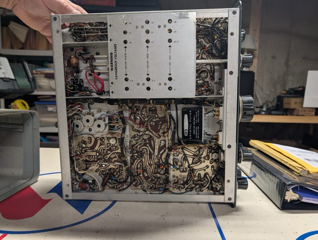
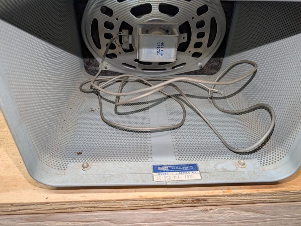
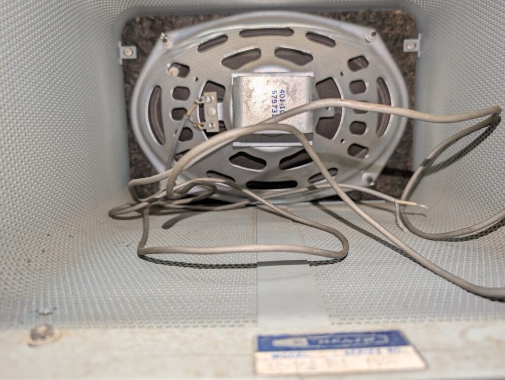
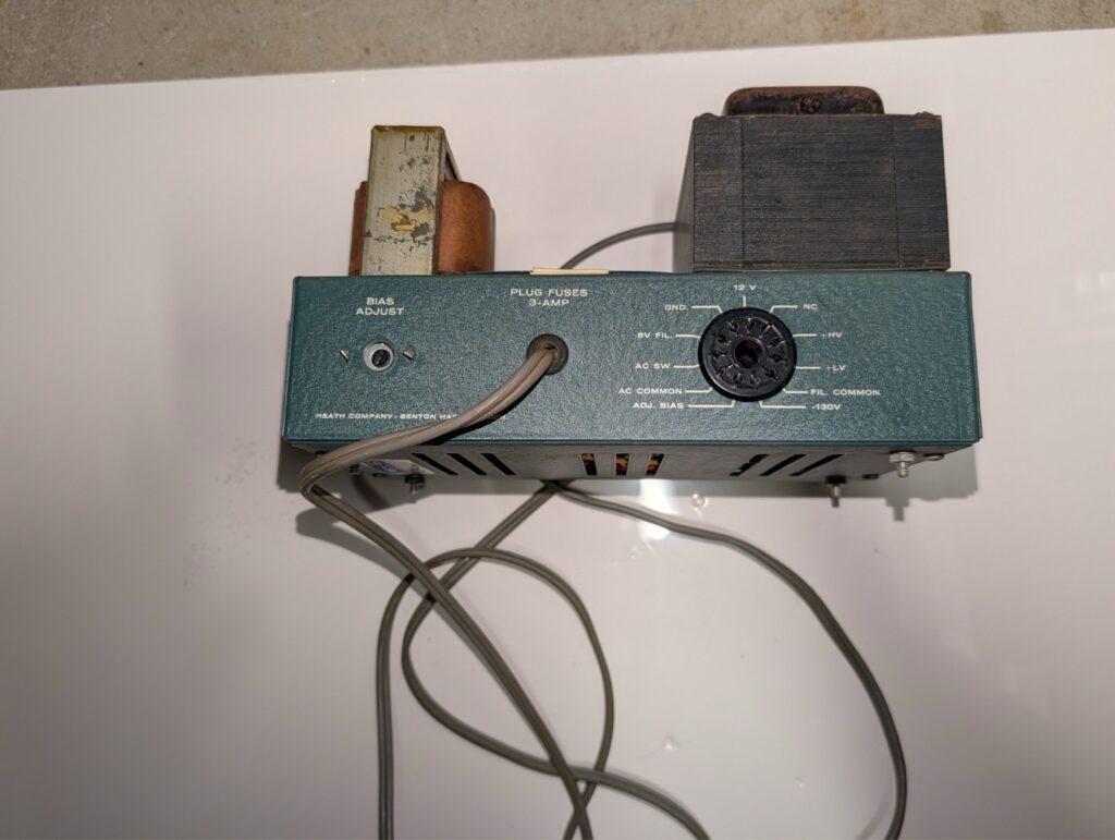
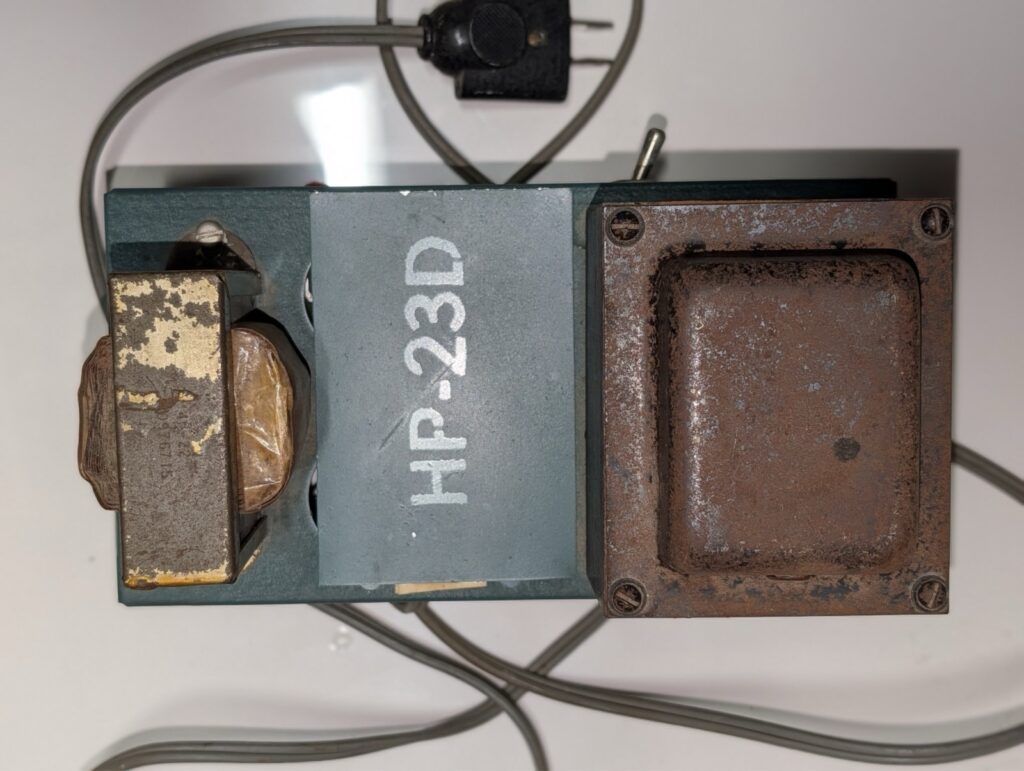
I know I’ll probably have more work to do on this rig before I put it on the air, but I wanted to know what I’m dealing with and see if there was any hidden damage from the exceedingly poor packing and delivery job done by FedEx. The power supply was apparently recently done, since it has a new board that essentially replaced all of the “guts” and is wearing a “HP-23D” marking – the sign of an updated power supply. I went ahead and plugged everything in, using my own SP-23 speaker since the SB-600 doesn’t have a plug on the end of the cable yet. I switched the power on and held my breath… and then let it out. No smoke, no screaming, all the pilot lamps came on. After half a minute or so I heard the very welcome sound of static from the speaker – the radio is alive!
Not seeing any obvious signs of distress, I checked the meter positions. High voltage was at 800 V as it should be, no other meter indications. I started going through the receiver alignment steps. A lot of the coild took some adjusting, though not a lot. I did find one “problem child”; the coils for the 28.5 and 29.0 MHz bands would not adjust, and it felt like there was something loose under the coil cover. I decided to leave it and come back to that later.
Toward the end of the process I turned the function switch to CAL and located the very strong calibration signal. No indication from the S meter, which I was able to fix by cleaning and eventually re-soldering the meter zero pot. With that fixed I got S9 +20 as expected. Switching to 40 meters, though, required significant retuning to find the marker signal. Hmmm. LMO? Something else? I made a note to chase that down and moved on.
Eventually I connected a random piece of wire a few feet long to the antenna jack and looked for a signal. 20 meters around the FT8 frequency is almost always a safe bet during the day, and so it was. I could hear some CW and FT8 as I tuned across the lower end of 20. Oddly, I guess it didn’t occur to me to switch to USB and move higher to listen to some SSB. Hmm.
After doing some more research and seeing a message thread on QRZ.com regarding crystals drifting as they age, I checked the heterodyne oscillator on each band. All are within .5 or .6 kHz of the expected frequency, with the exception of 40 and 80 meters. The 40 meter crystal is about 1.2 kHz low; I can live with that – though I may try a little series capacitance to “pull” it back closer to spec. 80 meters, however, is off by over 12 kHz. Of course a 12.395 MHz crystal is nearly impossible to find now. I did make contact with Steve, KW4H on QRZ, and he’s very graciously sending me one that’s closer to spec and can be pulled back on frequency.
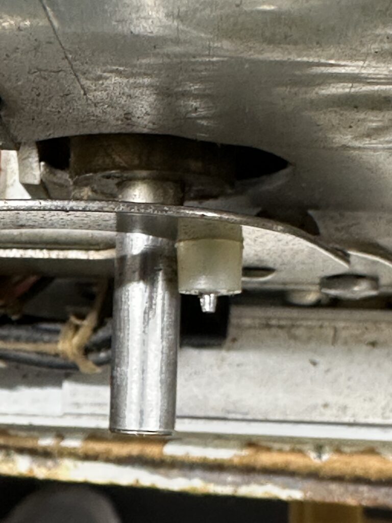
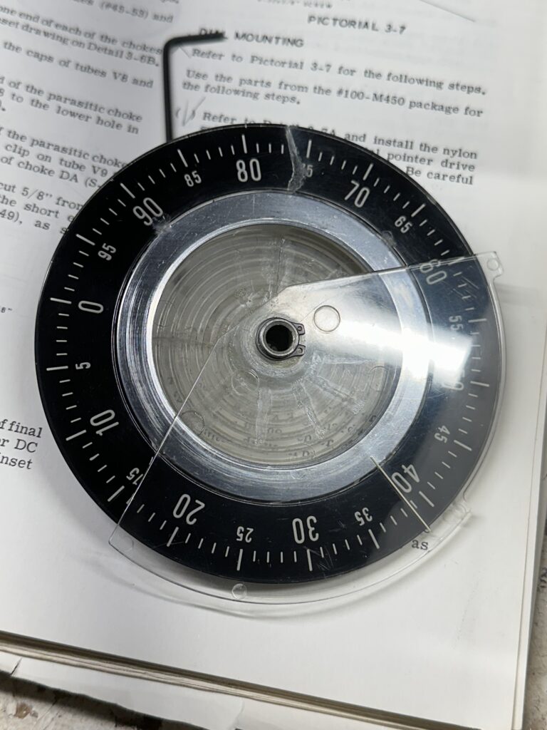
One reason some people go for the HW-101 over the SB-101/102 is the SB series’ rather more complicated tuning dial indicator. It’s a pretty involved mechanism. The main tuning knob turns a little pinch wheel, which drives a small diameter aluminum ring attached to the 100 kHz acrylic main tuning dial. Kind of a simpler (no doubt cheaper at the time) reduction drive than using a Vernier. I think the reduction is about 8:1, give or take.
On the back of the main tuning dial is a spiral groove. There is a sliding pointer above the main dial that indicates the 100 kHz segment you’re in. So, each revolution of the main dial moves the pointer by one division, so you get pretty good resolution across 500 kHz of the band. That pointer is moved by a pivoting arm with a little nylon follower, a tiny nylon pin that rides in the spiral groove of the main indicator dial.
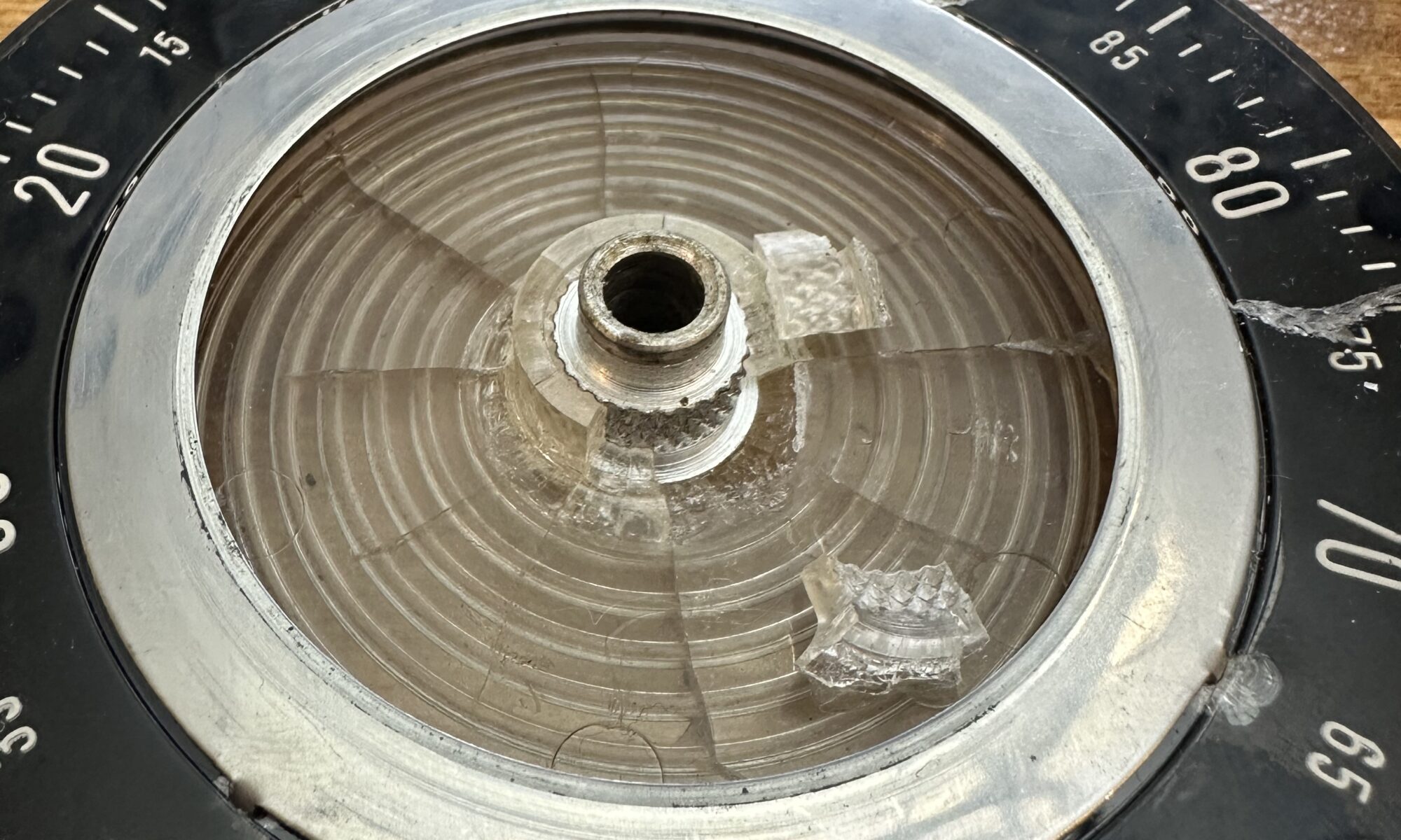
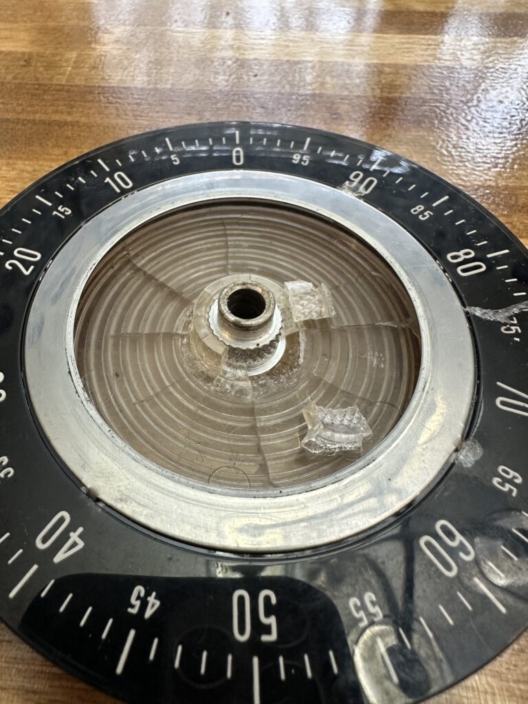
As you can see, the main dial has quite a bit of cracking radiating from the aluminum hub. One of the cracks goes all the way to the edge, running through approximately the 75 marking. The rest are more limited, but cracks never sleep. Also, the pin on the follower for the sliding pointer is broken off. So, there are two major problems to address. The minor issues include a bent skirt on the main tuning knob, and a bent pinch wheel for the tuning dial.
Of course none of these parts are in production any longer, and no new reproductions are being made either. I haven’t seen any for sale on eBay. The only source of parts, I suppose, would be other radios in the series to part out – and hope that they’re better, not worse. Rather than try to scrounge replacements, I decided to repair what I have. If I’m successful, the only thing I don’t think I can really fix is the cosmetic crack through the dial. If I get everything working, and mechanically sound enough to remain working, I can live with that. At some point I guess a new overlay could be made for the tuning dial, since it’s opaque. There are pilot lamps on either side to illuminate the dial, but it’s not backlit.
I began by getting everything taken apart and taking some measurements. The spiral groove seems to be around .060 or so; a .050 pin rides perfectly in it. After taking stock of what I have around and doing a little web research, I decided to try fabricating a new pin. I ended up chucking an M2 metric screw in a drill (a stack of nuts lets the drill chuck grip it) and turn it while filing the tip in a sort of ghetto lathe kind of arrangement. A little bench metal lathe would really have come in handy here. I’d have preferred to just fabricate the whole thing out of Delrin or something. Anyway, turned it down to around .050 – .055 until it was a smooth fit in the groove, and smoothed the pin as best I could. I drilled a slightly undersized hole through the nylon bit and secured the whole thing to the pivot arm with the pin sticking through the nylon. Honestly it would have been a lot easier to just use a few washers and a nut on the screw.
I used some water-thin acrylic glue and brushed it on each of the cracks, front and back, to try to seal them us as well as I can. I used Tamiya model glue but there are other brands that would work well. Not CA glue, actual solvent model glue. Anyway, I also glued the broken hub pieces back in place and clamped them while they dried, just for mote support and stability. Gluing the big crack left a mess on the front of the dial, so I used Micromesh pads followed by Novus plastic polish to clean that up and leave the dial face smooth and polished. I also used Novus on the fan-shaped index line piece, as it was pretty well scuffed. It’s not perfect, but I think it looks pretty good for a 50-plus year old piece of plastic.
I’ve been thinking about this for a while. Back when I was first getting interested in ham radio, one of the things I loved doing was drooling over the latest Heathkit catalog. Years before I began I was lusting after the H-8 microcomputer, the ham gear was the stuff of dreams. I’d have loved to have a nice SB series station. I eventually bought a slightly used HW-16, but the SB-401/301 or the SB-101 – or especially the SB-104 – those were the ticket.
Of course by the time I could actually afford anything, Heathkit had stopped making ham radio kits. The old rigs faded into the sunset as new, solid-state equipment took over.
So now I’m older, not flat broke, and the gear is of course comparatively a lot cheaper. I’ve had and used and enjoyed several solid-state rigs, and in fact still own a Kenwood TS-850S. Not exactly super modern, but far removed from tubes and mechanical dials. I do find joy in operating the old HW-16, though, and got to thinking about something a little more capable but of similar vintage.
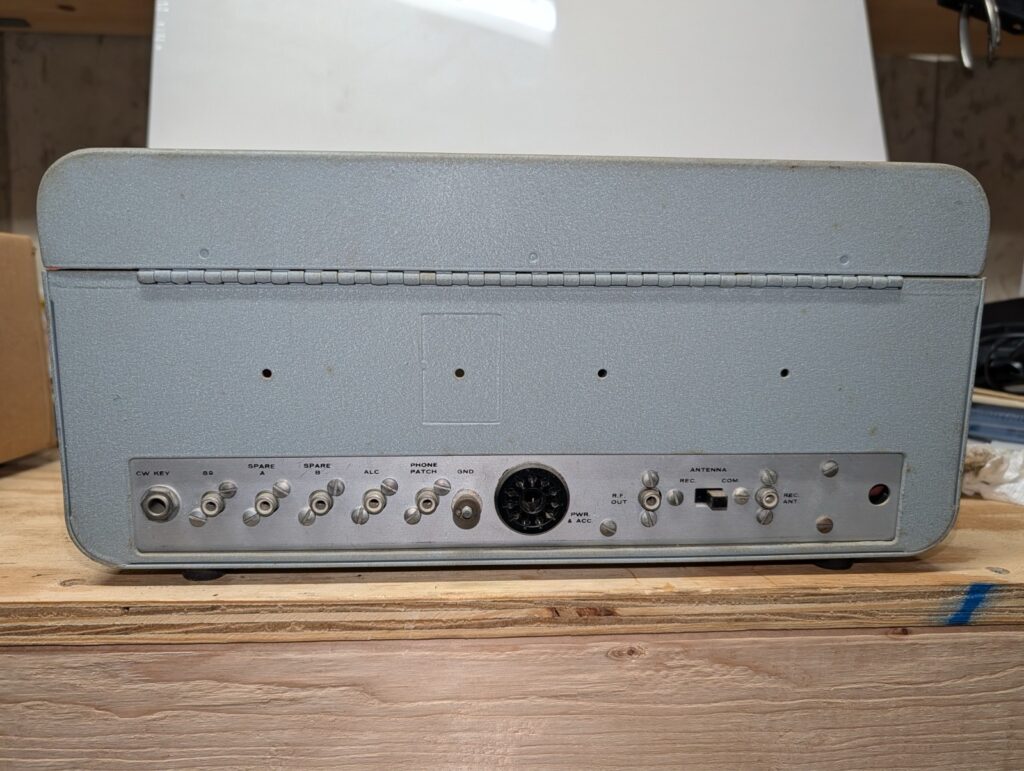
To make a long story short, yesterday Fedex delivered a badly mangled box containing a mercifully well cushioned SB-101 CW/SSB transceiver, a matching SB-600 station speaker, and the HP-23 power supply that provides the various voltages needed by the tube equipment. It’s been in storage for decades, is pretty grungy, and has a few minor mechanical issues – all of which I knew or expected when I bought it. The plan is to do a complete restoration. Electrical, mechanical, cosmetic – which, fortunately, seems like it will be the easiest part; the cabinets and paint seem to be in great shape. The SB-101 is extensively documented not only in the Heathkit assembly manual – which of course I got with the gear – but by countless hams and magazine articles since. If there’s a little tweak or fix to get it running at peak performance, that information is easy to find.
I didn’t get detailed “Before” pictures, but I did pull some from the eBay listing that show the condition. “Decent but grubby” I think captures the cosmetics.
The left front fender is beyond saving, at least for me. Too much rust and damage from previous “repair” work done in the worst way imaginable. Sheet metal had been tacked over the top of a big rusted-out hole with no attempt to either remove the bad metal or stop the rust, then it had been covered up with filler, The nose of the fender was also rusted out, so I’m not going to even try. The fender will contribute its sound sheet metal to my welding learning curve; I’ll chop it up and teach myself to butt, lap, and rosette weld with it. The jusry is out on the right fender, but it will likely go to the scrap yard as well.
There is evidence of old collision damage on the right front. The radiator support showed signs of having been creased and pulled back out, by way of a line of small holes apparently drilled to use a dent puller. It was rusty and bent. I decided to replace it with new. Likewise the right front fender apron had rust holes under the battery as well as some old collision damage. I decided to replace that along with the radiator support. A few days of drilling out spot welds with a spot weld cutter and I had the support loose and separated from both aprons, then got the right front apron out. Removing the front crossmember took longer, as there are a LOT of spot welds. Many are in places I can’t get to with a drill, so I used a cutting wheel on the angle grinder to cut loose everything I could. Drill, grind, cut, chisel, repeat. Long story short, it’s out. Then I found one of the strut rod supports is damaged as well, but I think I can probably straighten it out. The damage is more cosmetic than anything.
With the old sheet metal out of the way I started test fitting the new parts. The radiator support fits fine, but I’m wishing I’d bought a different part. NPD sells the support and crossmember as separate parts or already welded together. I bought the pre-welded assembly, thinking it was less welding that I’d have to do. If I’d seen how things went together, I’d have bought the pieces separately. I’ll likely end up buying a spot welder anyway, and that would have been a better way of assembling this stuff. As it is there’s a tab on the support that needs to be welded to the frame rail, but it’s covered by the crossmember so there’s no way to get in there and spot weld it. I’ll need to make some exposed seam welds for that. Not a big deal, but if I were doing it again I’d do it differently.
The fender apron seems to be about 3/16″ too far forward. I looked at my options for fixing that. I could probably just leave it as is; the misalignment is small enough that I’m pretty sure I could adjust the position of the fender to compensate. I don’t want to do that; it just seems like begging for problems later on. I don’t want to try to re-form the flange all the way down that apron. On the back end of the apron I think I can just oval out the bolt holes for the outer shock cover and move the whole part back the 3/16.
For now I’m going to get the parts lined up correctly, finish dry-fitting them, and leave them off. It will make getting the transmission and front end parts out easier. I want to get everything cleaned up as much as possible before starting to weld, just so I know everything that needs to be done.
I’ve been doing some work on the Mustang lately. I spent a week or two cleaning up and rearranging things in the garage to get more room to work on the two projects there – my airplane, and the Mustang. Now I can get to much of the car without needing to move things around. It’s far from perfect, but it’s quite a bit better than things have been for a while. With some time and some space to work, I started assessing the scope and severity of the issues that need to be fixed.
I think I’m adopting a new strategy for the car. I’ve been reluctant to really get into the project due to the enormity of the task list. Floor pans, trunk floor, quarters, wheel houses, on and on and on. But if I do nothing, then nothing gets done. The engine is ready to go in. I think I’m going to just start from the front and work my way back. With the car done from the front seats forward I’ll be able to drive it, which will give me a lot more flexibility. Accordingly I decided to:
Fix the front end sheet metal
Clean up the engine compartment
Pull and rebuild the transmission
Pull and rebuild the power steering components
Overhaul the front suspension
Install the front disc brake conversion upgrade
Fix the perforated firewall
Fix the floor pan welds
Drop in the engine and transmission
At that point I can drop in a seat and drive the car. I like the idea of being able to drive it, if only to make it much easier to move it around, for example to back it into the garage to work on the rear half of the car.
I haven’t flown since late July of 2022, for a variety of reasons. Yesterday (10/1) I met one of my partners and flew 1.1 hours. We left Millard (KMLE), flew toward Scribner (KSCB), decided halfway there that visibility wasn’t encouraging in that direction, and diverted to Wahoo (KAHQ), I did a full-stop landing at Wahoo, taxied back, took off, and returned to Millard. There was just enough gusting crosswind at both airports to make things interesting.
Obviously I’m rusty. It took a few minutes to get comfortable again, and it will take a few hours of flying time before I’m proficient, but I think I’m on the way back to flying again.
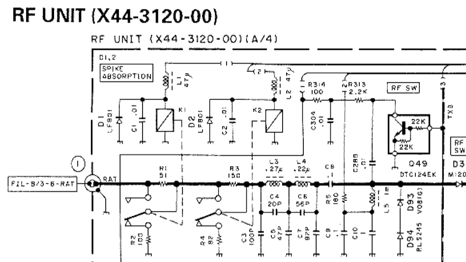
With the display fixed, I set out to do some alignment and adjustment on the TS-850. One thing I encountered was an issue with the attenuator. The 850 has two front panel buttons to switch in 6 and 12 dB attenuators, or both for 18 dB. One thing I had noticed was that the 6 dB attenuator seemed to work, but any time the 12 dB attenuator was switched in it completely killed the signal. Looking at the schematic, the only thing I could spot as a cause for that would be resistor R3 being open. I decided to pull the RF board and investigate.
With both attenuators off, relays K1 and K2 are both actuated. The signal from the antenna passes through K1 and K2, bypassing resistors R1 and R3. When the 6 dB attenuator is switched on, K1 de-energizes and puts a 6 dB resistive divider (R1/R2) in the signal path. The same method is used for the 12 dB attenuator (R3/4), activated by dropping relay K2.
Once I got the RF board out, the bottom of the board plainly showed that I was not the first one here. Portions of the board underneath the attenuator section were scorched, some SMT resistors were missing, and a 1/4 W resistor was soldered in place of R1. There were signs that some other components were damaged as well. I unsoldered and removed the “rework” resistor and found it to be the wrong value. Oddly, the board doesn’t match the diagrams I found in the service manual I found on line — a couple of the resistors have been replaced with pairs of resistors in parallel. That added some additional challenge to the process as I figured out the changes.
Eventually I found that something had damaged both R1 and R3. I found 1/8 W resistors of the correct values (51 and 150 Ohms – I had 50 and 150, close enough) in my parts stock. With those soldered in place of the defective SMT parts, I put it all back together and powered the rig back up, and got… nothing. Static. My little Elecraft XG2 signal generator was pushing 50 mV into the antenna jack, and the rig couldn’t hear a thing. I fed the signal directly to L3 and was able to hear it – weakly. So, back out comes the RF board.
Some probing with the DMM found a near dead short (1.4 Ohms) from the tail end of the attenuator at K2 to ground. Obviously that was a problem. Eventually I found capacitor C3, a little 100 pF SMT part, shorted. I removed it from the board and re-tested – now I can clearly hear the signal from the XG2, AND both the 6 and 12 dB attenuators work as they should. I don’t have a replacement for C3, but it’s part of a low-pass filter that I’m not terribly worried about right at the moment. I’ll pick up a 100 pF cap and replace it at my next opportunity. I also don’t know why it failed in the middle of a repair. It obviously wasn’t shorted before I started troubleshooting this issue, as I was able to receive signals off the air. All I can figure is that maybe it was physically damaged but not completely failed, and the probing or heat from the nearby soldering iron did it in. No matter – capacitors are cheap.
Now, on to the next issue — the S meter. It doesn’t “S”. Even with a 50 mV signal, there’s no reading on the meter; I’ll have to go through the alignment steps again to see if I can figure that out. Unfortunately that part of the procedure calls for a more capable signal generator than what I have. I should be able to get in the ballpark with the XG2. The service manual calls for 6 dB and 32 dB – or 1 uV and 40 uV. The XG2 will generate signals on 80, 40, and 20 meters at 1 or 50 uV. I should be able to set the S meter to read pretty close, assuming I don’t run into some OTHER issue that requires ripping the radio apart again.
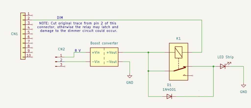
Note: edited 7/28/25 and image updated 2/27/26; I refined this by removing one diode and dropping the supply voltage a bit. The updated schematic below reflects that change.
A few days ago, I replaced the dim and occasionally flickering CFL backlight from my TS-850 with a length of LED strip light. At first I was pretty happy with it – until the first time I tried to transmit, that is.
To recap, I ran power from the power switch white lead (switched input DC voltage) as I had seen in a couple of Internet posts. I ran that through a total of four 1N4001 diodes in series. The 13.8 V supply voltage really drove the LEDs too bright, and two diodes provided enough voltage drop to make it more reasonable — though as I used it, it became apparent that it really could have used another series diode. The second pair of diodes were bypassed by the display dimmer switch. All well and good; it seemed to work fine.
Then I connected a new power supply thoughtfully provided by a friend (thanks, Dan!), connected a dummy load, and went about setting up the rig for use and testing the power supply’s performance. I set the supply voltage at 13.75 V, and as soon as I started transmitting into the dummy load I noticed that the display would dim quite a bit. In fact, if I set the dimmer switch on (display dimmed) and transmitted, the display would blank entirely. Not good!! It turns out that the white wire on the power switch – well, I don’t know what all is between it and the input; the schematics in the TS-850 service manual are almost impenetrable. Wherever it’s coming from, that line will sag down to 11 V or even lower when the rig is transmitting. It’s totally unregulated. Obviously I needed a better solution.
It occurred to me that, since I’d replaced the capacitors on the display board, maybe the original backlight would be OK. I re-installed the tube and re-connected the inverter and fired up the transceiver – but the display was still pretty dim. After seeing it nice and brightly lit by the LEDs, I wasn’t about to go back to squinting at that. The serial number on my rig indicates it was manufactured in December of 1993; I guess thirty-odd years is a bit of a long time to expect a CCFL backlight to stay healthy. I spent a little time looking for a suitable replacement tube, but aside from not finding one with the right length, I have no idea what voltage is being produced by the inverter – and I’m really not in the mood to screw with it.
After some pondering, I settled on a new approach. I ordered some DC-DC boost converters from our favorite purveyor of just about everything (Amazon). These will take a wide range of input voltage – 2 to 24 V claimed – and convert it to a higher output voltage – 5 to 28 V they say. All I need is to bump the regulated 8 V power up to around 12 V to drive the LED strip. I can adjust the output to get the brightness I like, then switch in the diodes to drop it a little for the dim display setting. These boost converters cost well under a buck each, so I’ll keep a couple around just in case they don’t last as long as I do. I’ll make sure to bag one or two up, along with a replacement LED strip, to go with the transceiver when I (or my heirs) sell it. I’m not going to bother posting a link to the Amazon item because I’m sure in six months it will be a dead link. Just search for “DC-DC step up converter” or similar and sort through until you find a suitable model for you. You could also design one from scratch for extra ham credit.
I designed the circuit below to be as flexible as possible. You don’t need to modify the dimmer switch board; it remains entirely untouched. No soldering to the power switch. All of the wiring is completely on the display board. I happened to have a couple of small SPDT relays with 12 V DC coils on hand, but designed it so that you could use much any relay that has a normally-closed contact (so, SPST-NC or SPDT). These relays can be had dirt cheap. The coil voltage just needs to be 12 V give or take a little; nothing in this whole exercise needs to handle more than maybe 130-150 mA.
About the only inconvenience I ran into is that the DIM switch circuit doesn’t go directly to the CCFL inverter connector, so you’ve got to solder a wire to one of the ribbon cable connector pins. Not a huge deal. No major modifications to the display board are needed, but you will need to cut the small trace that runs from Pin 2 of CN1 (the display dim signal) to one of the SMT resistors in the board. That circuit feeds a PWM driver chip, and the circuitry there will prevent the relay from releasing once it’s turned on. That means that if you dim the display without first cutting the trace, you won’t be able to un-dim it until you turn the rig off. So, a minute with an X-Acto knife does the job.
In this circuit, the 8 V supply is picked off of the original inverter input connector and fed to the DC-DC converter. Adjust the output of the converter for 12 V or give or take a bit, whatever level gives an appropriate brightness for the LED backlight. The output of the boost converter is connected to the relay coil as well as the relay’s NC contact. The other side of the relay coil is connected to the DIM switch input from the front panel, which is grounded to dim the display and otherwise floats.
With the display switch set for full brightness, the relay coil is not grounded and the relay is not energized. Current flows from the DC-DC converter to the LED backlight through the NC contact of the relay, bypassing the diode.
With the switch set to the DIM position (pushed in), the switch grounds one side of the relay coil and energizes the relay. Current now reaches the LED strip through the diode, which provide enough voltage drop to dim the display. Diode choice is not terribly important and can be changed to suit your individual preference for the difference between full brightness and “dim”. You could add a second diode in series if needed. My LED strip draws around 130 mA at full brightness; a 1N4148 would probably do the job as well. I just didn’t happen to have any on hand, which is strange given the thousands and thousands I’ve bought over the years for various kits I sold.
Installation is pretty straightforward. I removed the CCFL tube and slid the adhesive-backed LED strip behind the LCD, then used a piece of tubing I happened to have on the bench to reach through and make sure it was securely stuck down all the way through. A piece of dowel would be good too. I removed the inverter and its connectors entirely – no sense leaving that there with the tube gone. I used CN3, the inverter supply connector, for the ground and 8 V inputs to the boost converter. I soldered the diode assembly directly to the relay, then used some hot-melt glue to stick the relay to the board. The DC-DC converter then mounts onto the relay with more hot-melt glue – just be careful to keep anything from shorting. There’s enough room to sandwich a little spacer of balsa or plastic or something in there if needed. The converter I used has an adjusting pot that I made sure was facing upward, so I could adjust it from the top.
I left the LED strip disconnected during the initial power-on “smoke test”. I had no idea what voltage the little board would be putting out. It turned out to be 18 V. I adjusted that down to 12 V and powered the rig off. Then I soldered the LED wires in place and powered on again. I tested the dim function and found it to be too dim on that setting, so I tweaked the voltage a bit to give me a good display on both settings. This will depend on your particular LED strip, but in my case I ended up with the output of the DC-DC converter set to 13.3 V. My first iteration of this used two 1N4001 diodes in series; I later switched to using a single diode and reduced the supply voltage to 11.5 V. That gave me about 10.75 on the dim setting, and the display looks great either way.
Now, why so complicated with the relay? Can’t you just use the dimmer switch directly without the relay? Well… sort of. Unfortunately, the way that switch is connected on the little switch daughter board, isolating the pins to use for this is a challenge. I ended up having to de-solder it from the board, cut off a couple of leads, and re-solder it. It’s too much surgery and is irreversible. I ended up buying a replacement from eBay; fortunately, it was relatively cheap, but obviously no new ones are being made, and I wanted to present a solution that involved as little butchering as possible.
Since this is a modification that may confuse someone encountering it for the first time, my plan is to pack up the schematic, a spare boost converter or two, and a spare chunk of LED strip and keep it with the rig. Some day someone else will probably own this transceiver, and they may appreciate not needing to reverse engineer all of it.
And finally, yes, I did see the packaged solutions available from a couple of places. Both are coming from outside the US, with all of the delay and shipping expense (and uncertainty) that comes with it. They’re also pretty spendy. I figure I’ll have under $2 worth of parts wrapped up in this project, and a left-over pile of little DC-DC converters and several feet of LED light strip that will probably soon adorn my 3D printer or something.
While pondering new ways to enjoy the delicious, pure maple syrup I made myself from our own maple trees, I invented a new drink. I call it the Montpelier, named for the maple syrup capital of the USA. While perhaps not as famous as our cousins to the north, the US does produce its fair share – or some share at least. Vermont is number two in the world in maple syrup production, right behind Canada. I also thought the name was appropriate since the drink is to some degree adapted from the Manhattan.
If you like your cocktails a bit booze-forward, like an Old Fashioned or a Manhattan, this might be your new favorite. It’s not overly sweet, but has enough complexity and rich flavor to make it a solid pick.
Two measures of Bourbon (or rye, if you prefer)
One measure of sweet vermouth
A teaspoon of pure maple syrup. I use my own home-made syrup, boiled down from the sap of the maple trees in my own back yard. If you don’t make your own maple syrup, Vermont maple syrup is preferred over the Canadian stuff – just because it’s named the Montpelier, of course. Use what you must, though! Just not that fake garbage you see ten-year-olds pouring over their hotel lobby pancakes.
For a properly American garnish, try Peppered Maple-Glazed Bacon. Glaze a strip of thick-cut bacon with maple syrup and a bit of fresh ground black pepper. Bake until crisp, cut into short lengths and skewer it for the rim.
Add all of the ingredients to a mixing glass with ice. Stir until well chilled and properly diluted, about 30 seconds or so. Strain into a coupe, or serve over a large ice cube in a rocks glass.