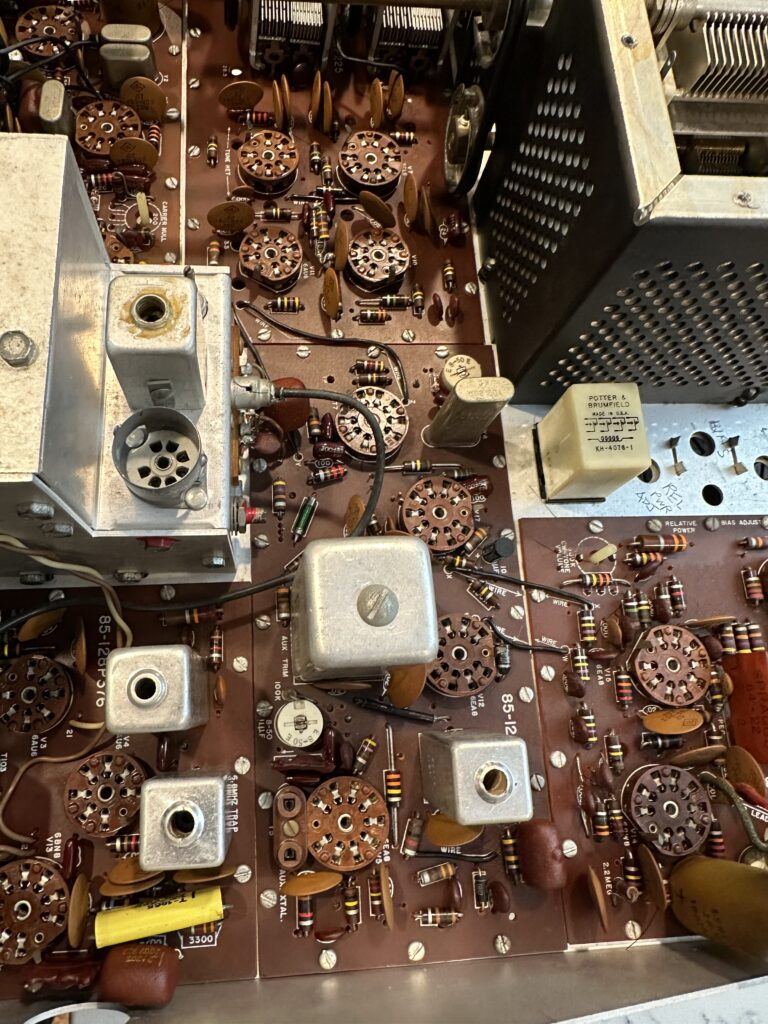
Better late than never! While I wait for the new 80 M crystal to arrive, I made use of Will, N5OLA’s excellent information to do a quick check of the resistors in the rig. Will has some incredibly nice and useful videos on YouTube detailing his process for restoring and repairing Heathkit SB and HW line radios, and has been very kind and helpful in sharing information. He’s even supplying me with a replacement for the broken oscillator coil plaguing the 28.5 & 29 MHz bands on this transceiver.
I was looking for badly out-of-spec carbon composition resistors. When they drift, they always drift “upward” – meaning, higher resistance. My strategy is to check them in-circuit. A lower reading than spec is fine, it just means I’m reading the resistance of other parts of the circuit. A higher-than-spec reading must mean that the resistor has a higher resistance than it should. Anything at 15% or beyond gets replaced. For example, a 47K Ohm resistor that reads 51.7K is fine; it’s within spec even when new. If it hits 54K Ohms, though, it’s getting replaced. I realize that this approach may result in out of tolerance resistors being left in place – but I’ll chase those down if and as problems occur. The alternative is treating every resistor in the rig like a dog – lifting one leg to check the value. Yeah, I just made that up. Sorry.
I found a dozen or so resistors out of tolerance and put an order in at Digikey for those, as well as a couple of other small parts. I also ordered a re-cap kit to replace electrolytic and mylar capacitors that don’t age well. Hayseed Hamfest sells a nice little kit with the caps needed, and they’re no more expensive than ordering the individual parts from Digikey. I’ll give a ham the business.
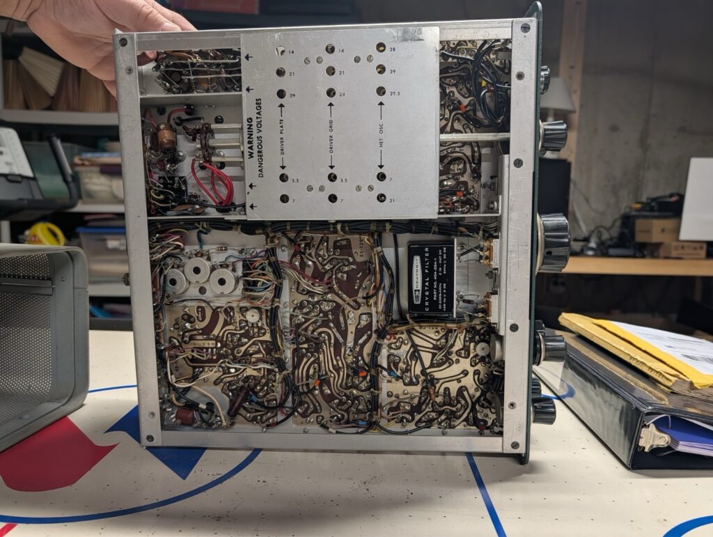
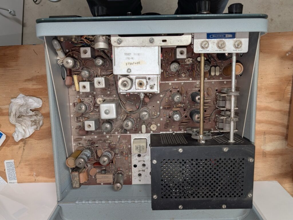
So I’m waiting for a crystal, some resistors, a coil, and a bag of capacitors. Rather than chase down problems that those parts will or might fix, I decided it was time for a bath. I removed all of the tubes and tagged them with their locations using masking tape on the side of each tube. Then I gave the top side of the circuit boards a liberal spray of Dawn Powerwash and gently scrubbed everything I could with a small paintbrush and an acid brush, trying to loosen any dirt, grime, and oil from the boards. I gave it a thorough spray rinse from the faucet and repeated the process. Then it was into the oven on the “warm” setting, about 125-150 degrees, for an hour to thoroughly and quickly dry everything off. I opened the oven door a couple of times to let the moist air out and let fresh, dry air in. Then I turned the oven off and let the rig sit in there to cool slowly.
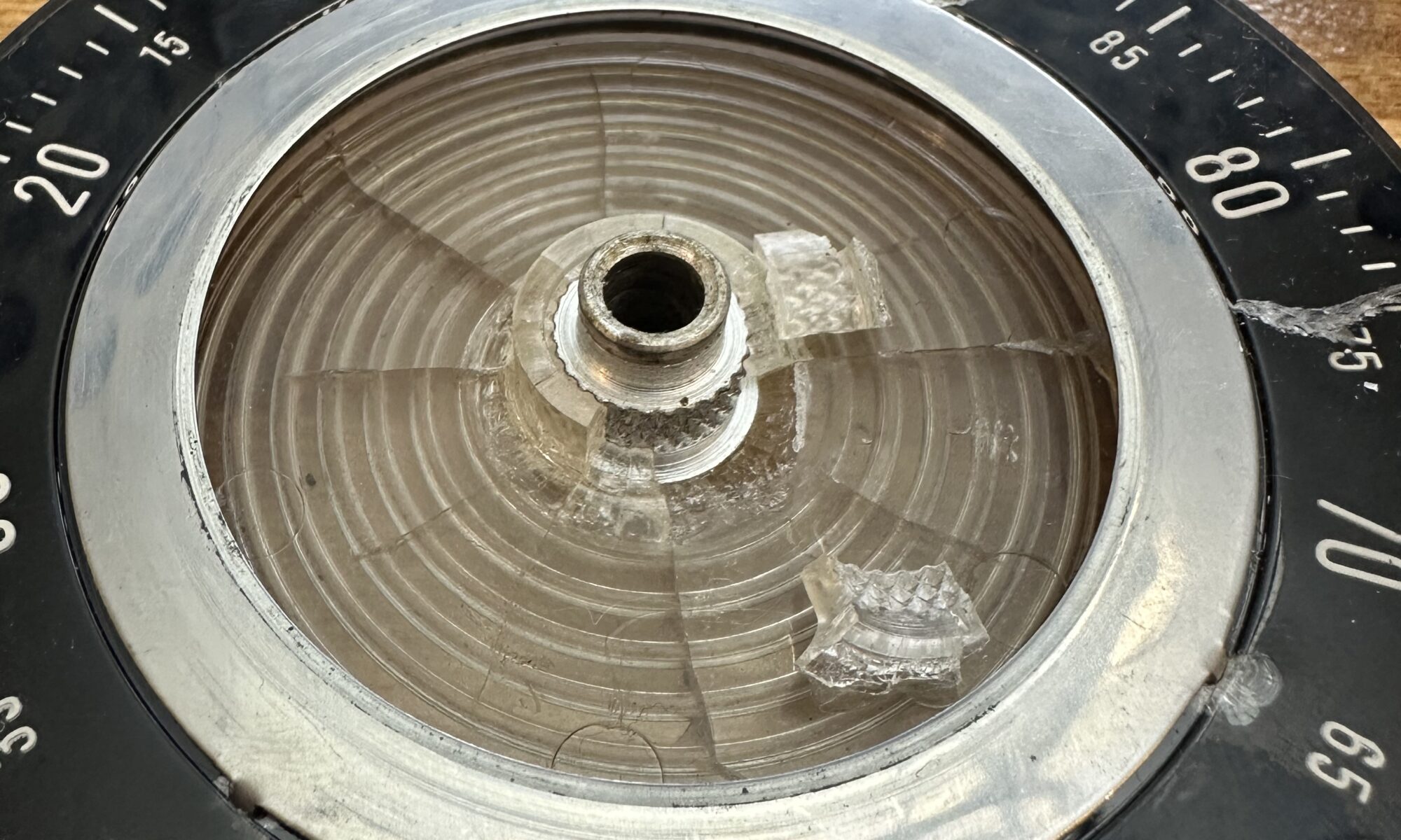
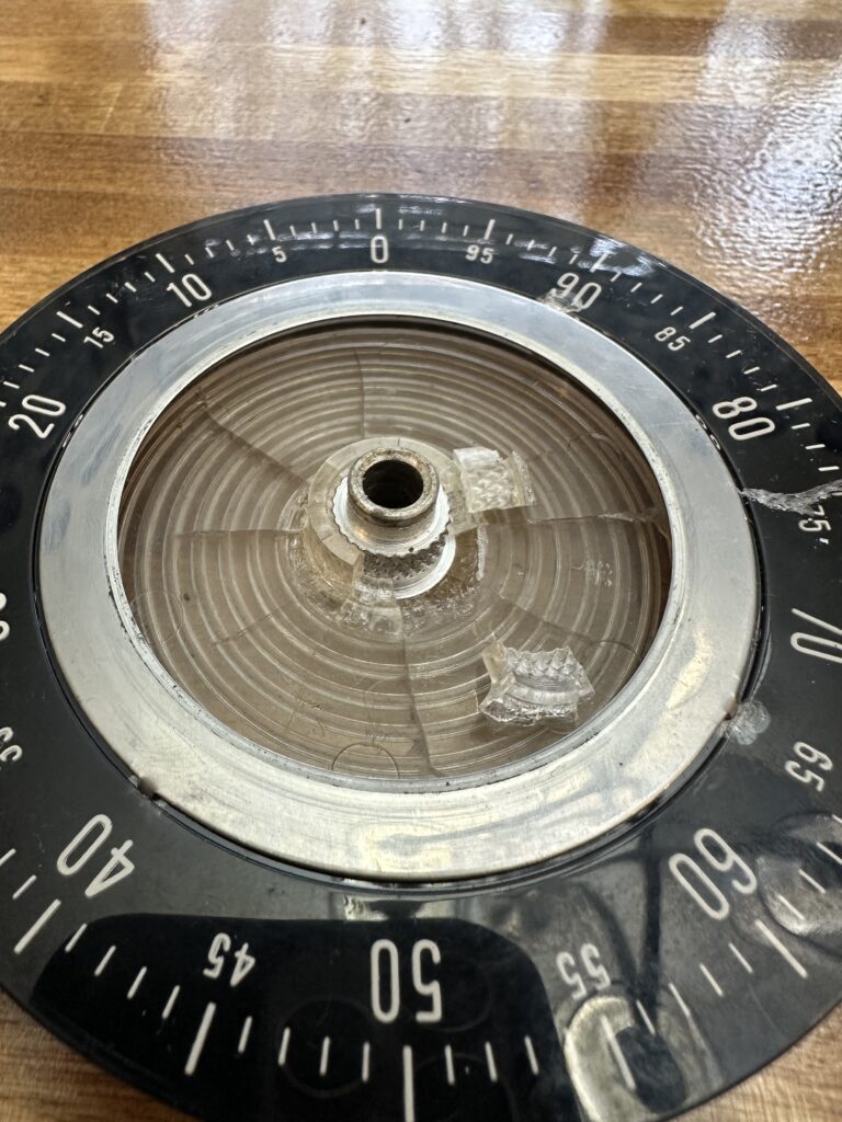
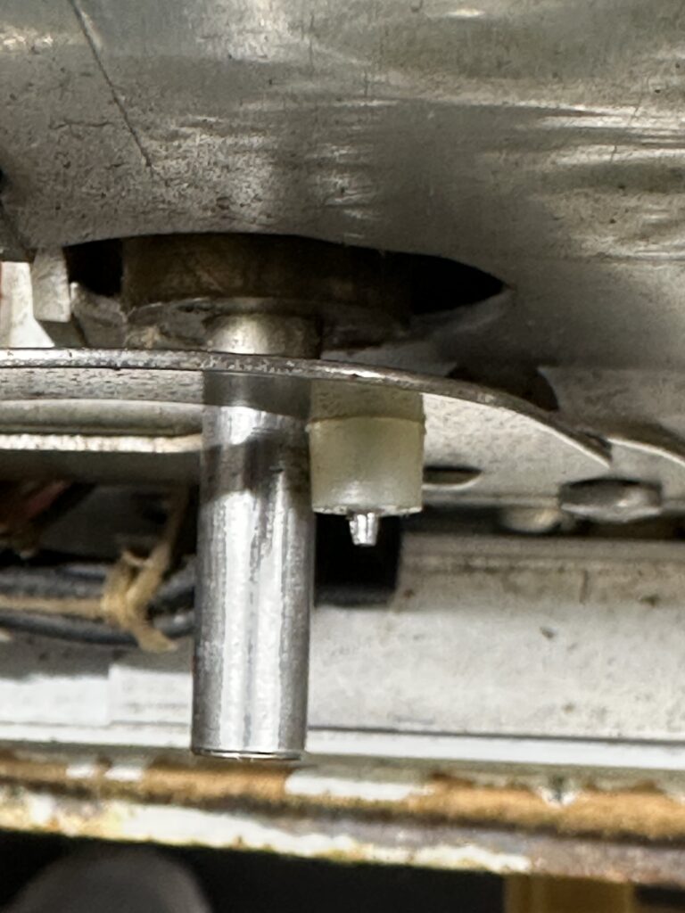
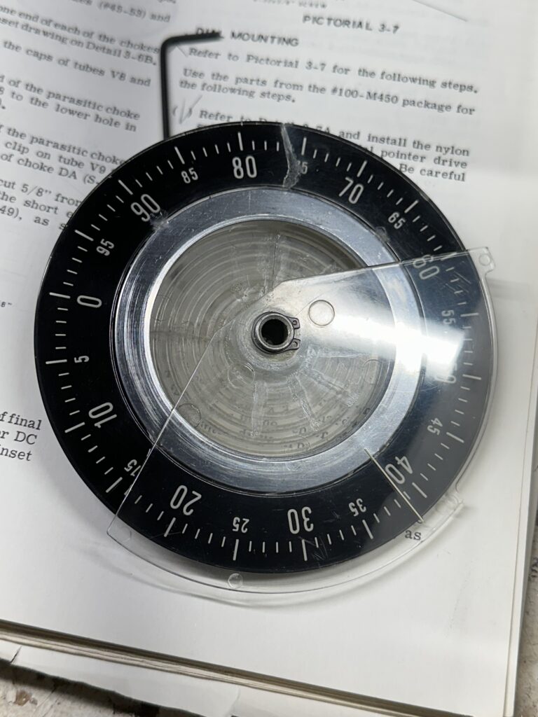
Once dry and cooled off, I checked for any remaining water and re-installed all the tubes. I decided to wait a few more hours before giving it a “smoke test”, and in the mean time decided to fix the main tuning dial drive. But that’s another post.