TS-850S attenuator

With the display fixed, I set out to do some alignment and adjustment on the TS-850. One thing I encountered was an issue with the attenuator. The 850 has two front panel buttons to switch in 6 and 12 dB attenuators, or both for 18 dB. One thing I had noticed was that the 6 dB attenuator seemed to work, but any time the 12 dB attenuator was switched in it completely killed the signal. Looking at the schematic, the only thing I could spot as a cause for that would be resistor R3 being open. I decided to pull the RF board and investigate.

With both attenuators off, relays K1 and K2 are both actuated. The signal from the antenna passes through K1 and K2, bypassing resistors R1 and R3. When the 6 dB attenuator is switched on, K1 de-energizes and puts a 6 dB resistive divider (R1/R2) in the signal path. The same method is used for the 12 dB attenuator (R3/4), activated by dropping relay K2.

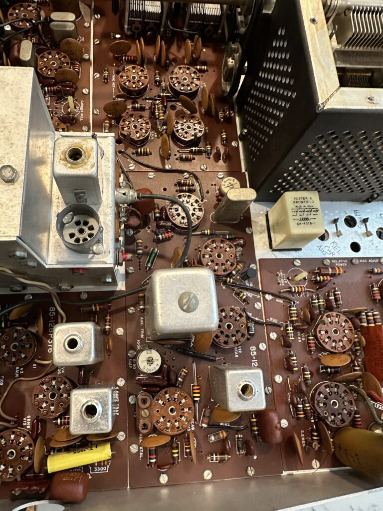
Once I got the RF board out, the bottom of the board plainly showed that I was not the first one here. Portions of the board underneath the attenuator section were scorched, some SMT resistors were missing, and a 1/4 W resistor was soldered in place of R1. There were signs that some other components were damaged as well. I unsoldered and removed the “rework” resistor and found it to be the wrong value. Oddly, the board doesn’t match the diagrams I found in the service manual I found on line — a couple of the resistors have been replaced with pairs of resistors in parallel. That added some additional challenge to the process as I figured out the changes.

Eventually I found that something had damaged both R1 and R3. I found 1/8 W resistors of the correct values (51 and 150 Ohms – I had 50 and 150, close enough) in my parts stock. With those soldered in place of teh defective SMT parts, I put it all back together and powered the rig back up, and got… nothing. Static. My little Elecraft XG2 signal generator was pushing 50 mV into the antenna jack, and the rig couldn’t hear a thing. I fed the signal directly to L3 and was able to hear it – weakly. So, back out comes the RF board.

Some probing with the DMM found a near dead short (1.4 Ohms) from the tail end of the attenuator at K2 to ground. Obviously that was a problem. Eventually I found capacitor C3, a little 100 pF SMT part, shorted. I removed it from the board and re-tested – now I can clearly hear the signal from the XG2, AND both the 6 and 12 dB attenuators work as they should. I don’t have a replacement for C3, but it’s part of a low-pass filter that I’m not terribly worried about right at the moment. I’ll pick up a 100 pF cap and replace it at my next opportunity. I also don’t know why it failed in the middle of a repair. It obviously wasn’t shorted before I started troubleshooting this issue, as I was able to receive signals off the air. All I can figure is that maybe it was physically damaged but not completely failed, and the probing or heat from the nearby soldering iron did it in. No matter – capacitors are cheap.

Now, on to the next issue — the S meter. It doesn’t “S”. Even with a 50 mV signal, there’s no reading on the meter; I’ll have to go through the alignment steps again to see if I can figure that out. Unfortunately that part of the procedure calls for a more capable signal generator than what I have. I should be able to get in the ballpark with the XG2. The service manual calls for 6 dB and 32 dB – or 1 uV and 40 uV. The XG2 will generate signals on 80, 40, and 20 meters at 1 or 50 uV. I should be able to set the S meter to read pretty close, assuming I don’t run into some OTHER issue that requires ripping the radio apart again.

TS-850 LED display backlight

Note: edited 7/28/25; I refined this by removing one diode and dropping the supply voltage a bit.

A few days ago, I replaced the dim and occasionally flickering CFL backlight from my TS-850 with a length of LED strip light. At first I was pretty happy with it – until the first time I tried to transmit, that is.

To recap, I ran power from the power switch white lead (switched input DC voltage) as I had seen in a couple of Internet posts. I ran that through a total of four 1N4001 diodes in series. The 13.8 V supply voltage really drove the LEDs too bright, and two diodes provided enough voltage drop to make it more reasonable — though as I used it, it became apparent that it really could have used another series diode. The second pair of diodes were bypassed by the display dimmer switch. All well and good; it seemed to work fine.

Then I connected a new power supply thoughtfully provided by a friend (thanks, Dan!), connected a dummy load, and went about setting up the rig for use and testing the power supply’s performance. I set the supply voltage at 13.75 V, and as soon as I started transmitting into the dummy load I noticed that the display would dim quite a bit. In fact, if I set the dimmer switch on (display dimmed) and transmitted, the display would blank entirely. Not good!! It turns out that the white wire on the power switch – well, I don’t know what all is between it and the input; the schematics in the TS-850 service manual are almost impenetrable. Wherever it’s coming from, that line will sag down to 11 V or even lower when the rig is transmitting. Totally unregulated. Obviously I needed a better solution.

It occurred to me that, since I’d replaced the capacitors on the display board, maybe the original backlight would be OK. I re-installed the tube and re-connected the inverter and fired up the transceiver – but the display was pretty dim. After seeing it nice and brightly lit by the LEDs, I wasn’t about to go back to squinting at that. The serial number on my rig indicates it was manufactured in December of 1993; I guess thirty-odd years is a bit of a long time to expect a CCFL backlight to stay healthy. I spent a little time looking for a suitable replacement tube, but aside from not finding one with the right length, I have no idea what voltage is being produced by the inverter – and I’m really not in the mood to screw with it.

After some pondering, I settled on a new approach. I ordered some DC-DC boost converters from our favorite purveyor of just about everything (Amazon). These will take a wide range of input voltage – 2 to 24 V claimed – and convert it to a higher output voltage – 5 to 28 V they say. All I need is to bump the regulated 8 V power up to around 12 V to drive the LED strip. I can adjust the output to get the brightness I like, then switch in the diodes to drop it a little for the dim display setting. These boost converters cost well under a buck each, so I’ll keep a couple around just in case they don’t last as long as I do. I’ll make sure to bag one or two up, along with a replacement LED strip, to go with the transceiver when I (or my heirs) sell it. I’m not going to bother posting a link to the Amazon item because I’m sure in six months it will be a dead link. Just search for “DC-DC step up converter” or similar and sort through until you find a suitable model for you. You could also design one from scratch for extra ham credit.

I designed the circuit below to be as flexible as possible. You don’t need to modify the dimmer switch board; it remains entirely untouched. No soldering to the power switch. All of the wiring is completely on the display board. I happened to have a couple of small SPDT relays with 12 V DC coils on hand, but designed it so that you could use much any relay that has a normally-closed contact (so, SPST-NC or SPDT). These relays can be had dirt cheap. The coil voltage just needs to be 12 V give or take a little; nothing in this whole exercise needs to handle more than maybe 130-150 mA.

About the only inconvenience I ran into is that the DIM switch circuit doesn’t go directly to the CCFL inverter connector, so you’ve got to solder a wire to one of the ribbon cable connector pins. Not a huge deal. No major modifications to the display board are needed, but you will need to cut the small trace that runs from Pin 2 of CN1 (the display dim signal) to one of the SMT resistors in the board. That circuit feeds a PWM driver chip, and the circuitry there will prevent the relay from releasing once it’s turned on. That means if you dim the display, you can’t un-dim it until you turn the rig off.

In this circuit, the 8 V supply is picked off of the original inverter input connector and fed to the DC-DC converter. The output of the converter is set to 12 V or give or take a bit, whatever level gives an appropriate brightness for the LED backlight. The output of the boost converter is connected to the relay coil as well as the relay’s NC contact. The other side of the relay coil is connected to the DIM switch input from the front panel, which is grounded to dim the display and otherwise floats.

Diagram of the new LED drive circuit
The LED backlight modification. After some experimentation, I removed one of the two series diodes.

With the display switch set for full brightness, the relay coil is not grounded and the relay is not energized. Current flows from the DC-DC converter to the LED backlight through the NC contact of the relay, bypassing the diode.

With the switch set to the DIM position (pushed in), the switch grounds one side of the relay coil and energizes the relay. Current now reaches the LED strip through the diode, which provide enough voltage drop to dim the display. Diode choice is not terribly important and can be changed to suit your individual preference for the difference between full brightness and “dim”. You could add a second diode in series if needed. My LED strip draws around 130 mA at full brightness; a 1N4148 would probably do the job as well. I just didn’t happen to have any on hand, which is strange given the thousands and thousands I’ve bought over the years for various kits I sold.

Installation is pretty straightforward. I removed the CCFL tube and slid the adhesive-backed LED strip behind the LCD, then used a piece of tubing I happened to have on the bench to reach through and make sure it was securely stuck down all the way through. A piece of dowel would be good too. I removed the inverter and its connectors entirely – no sense leaving that there with the tube gone. I used CN3, the inverter supply connector, for the ground and 8 V inputs to the boost converter. I soldered the diode assembly directly to the relay, then used some hot-melt glue to stick the relay to the board. The DC-DC converter then mounts onto the relay with more hot-melt glue – just be careful to keep anything from shorting. There’s enough room to sandwich a little spacer of balsa or plastic or something in there if needed. The converter I used has an adjusting pot that I made sure was facing upward, so I could adjust it from the top.

I left the LED strip unsoldered during the initial power-on “smoke test”. I had no idea what voltage the little board would be putting out. It turned out to be 18 V. I adjusted that down to 12 V and powered the rig off. Then I soldered the LED wires in place and powered on again. I tested the dim function and found it to be too dim on that setting, so I tweaked the voltage a bit to give me a good display on both settings. This will depend on your particular LED strip, but in my case I ended up with the output of the DC-DC converter set to 13.3 V. My first iteration of this used two 1N4001 diodes in series; I later switched to using a single diode and reduced the supply voltage to 11.5 V. That gave me about 10.75 on the dim setting, and the display looks great either way.

Now, why so complicated with the relay? Can’t you just use the dimmer switch directly without the relay? Well… sort of. Unfortunately, the way that switch is connected on the little switch daughter board, isolating the pins to use for this is a challenge. I ended up having to de-solder it from the board, cut off a couple of leads, and re-solder it. It’s too much surgery and is irreversible. I ended up buying a replacement from eBay; fortunately, it was relatively cheap, but obviously no new ones are being made, and I wanted to present a solution that involved as little butchering as possible.

Since this is a modification that may confuse someone encountering it for the first time, my plan is to pack up the schematic, a spare boost converter or two, and a spare chunk of LED strip and keep it with the rig. Some day someone else will probably own this transceiver, and they may appreciate not needing to reverse engineer all of it.

And finally, yes, I did see the packaged solutions available from a couple of places. Both are coming from outside the US, with all of the delay and shipping expense (and uncertainty) that comes with it. They’re also pretty spendy. I figure I’ll have under $2 worth of parts wrapped up in this project, and a left-over pile of little DC-DC converters and several feet of LED light strip that will probably soon adorn my 3D printer or something.

Getting back on the air – Part 2 (Kenwood TS-850)

I presently own three HF radios. The most capable of the three, the one I plan to use first, is a Kenwood TS-850SAT, which was manufactured in Japan some time in the 1990s. At the time it was at or near the top of their product line; one of the last of the non-DSP radios. It really is a pretty nice rig; maybe not quite as posh as a TS-930, but the power supply doesn’t die every time you look at it sideways.

Unfortunately, after several years sitting in a closet in my office, a couple of the front panel buttons were balky. Also, the display is an LCD backlit with a small CFL tube; as one would expect, either the CFL tube or its power supply is starting to fail, meaning the display occasionally goes blank. Time to take it apart again.

The switches were relatively easy to fix. With the switch board removed, they’re just common 6m square tactile buttons. I replaced the UP and DN buttons – only one was bad, but the new switches have a different actuating force than the originals, and I wanted the button feel to match between the two.

I removed the display panel and found that the inside of the plastic lens over the display was pretty well coated with a grungy tan film of dirt or, more likely, tar from a previous owner’s cigarettes. You can tell where the air flows through the radio by the brown deposits on the parts. It’s not bad bad, but I’ll clean up what I can while I’m in there. I spent a while with some lens cleaning solution, Q-Tips, and a microfiber cleaning cloth getting that cleaned off again.

While I had the radio apart waiting for the LED strip, I checked the DDS chips – these are Direct Digital Synthesis chips that generate the various frequencies used by the radio. Early TS-850s are known for developing problems with the carrier board that these chips are on. Fortunately, mine has the newer part number chips that are supposed to be good and not prone to failure.

The new LED display backlight was relatively straightforward. With the strip cut and stuck in place, I wired it to the white wire from teh front panel power switch. Too bright. It’s a 12V strip, and the power supply is at least 13.5. After some fiddling and experimenting, I ended up de-soldering the dimmer switch and removing two pins to isolate it from ground. Power now comes from the supply switched line (white wire of the power switch), through four 1N4001 diodes in series to drop the voltage to a good level for a dimmed display. The dimmer switch is wired across the second pair of diodes to bypass them for full brightness — in other words, two diodes for full brightness and four for dimmed. It works quite nicely, and the display is now nice and crisp and easy to read.

I still have no antenna up, but last night with about 8′ of wire strung across my office the receiver seemed to work a well as my FT-817ND receiving the very, very few signals I could hear.

Getting back on the air – maybe – Part 1

I’ve been a licensed ham radio operator, off and on, since about 1981. Early on I learned Morse code and the required knowledge to pass my Novice license test in ’81, and was issued the call sign KA5MSS. I passed the exam while we were living at Fort Sill, OK, but didn’t actually receive the license until we’d already moved to Atlanta for a six-month stint. Living in an apartment with nothing but a Heathkit HW-16, I didn’t get a chance to get on the air. In fact, I held KA5MSS for five years until it expired (and a Korean call sign, HL9CA, for the yer I was in Korea), having never gotten on the air

Later on, in the late 80s or early 90s, I took the Technician exam and was issued a new call sign, N0XAS. I upgraded to General class in 1994, and to Extra in 2002. I’ve operated with that call sign ever since it was first issued, making a lot of contacts. I primarily operated CW (Morse code) and much of that was QRP (using low power, 5 Watts output or less), but I’ve operated SSB (voice), VHF and UHF FM voice, packet, PSK31, and probably a few modes I tried once or twice and forgot about. I never got into contesting.

I could write a book about how I drifted away from operating – though a lot of it involved a new side business developing and selling ham related kits and even a fully assembled Morse keyer. It was nice, but it did eventually consume all of the time and energy I might have devoted to operating. A new steel roof over my attic dipole antenna drove the final nail in the coffin.

I’m hoping to get back in the air before winter sets in, so I’ve been working toward that. I need to get my station set up again, get an antenna up and working, get up to speed on changes to the regulations and operating practices since I was last active, and get my Morse code copy speed back up to snuff – at least 10 WPM solid, preferably 13 or better. More to come.

Various stuff…

First of all, sue me…  I’m loving the iPhone.  I never thought I would.  There are a few little annoyances, but overall it’s a great little widget.

Went to the Ak ARC flea market Saturday.  I had a table to sell kits, but I don’t know why I bothered.  I did (just barely, maybe) cover my breakfast, the table and my gas to drive there and back, so I guess it was OK.  Honestly, I think most of the stuff for sale was the same crap I’d seen last year.  There was, however, a table set up by the Omaha Maker group, and separately a ham had a 3D printer running printing out something or other, I never did figure out what.  So why did I go?  It was good to see and talk to some of the hams I only see once in a while.  Jack WA0SAQ was there, Dave WJ0Z and some others I seem to only see once every year or five.

I did some CNC engraving on the end panels for a new flavor of PicoKeyer.  I think it turned out pretty well.  It will be a little extra work — OK, a lot of extra work, but I think it will be worth it.  This will also probably be the motivation I need to finally break down and make a better fixture for the end panels I use for the boxes.  Maybe something I don’t have to stand there and hold each one in place.  It would be a worth a lot to me to be able to not stand there the whole time the mill is running, holding parts and trying to avoid getting an end mill through a thumbnail.  McMaster, here comes an order!

And…  some days I miss not having something that looks like airplane parts in the garage.  In a couple of weeks, though, I should have a “canoe” going and by Spring it should be looking airplane-y again.

That is all.

Just too cool.

I was using my new-ish Owon DS7102V scope tonight to troubleshoot a problem with a PicoKeyer firmware function.  After I got it fixed, I took a screen shot to show just how impressive the capture buffer is on this thing…

Yes, that’s “DE N0XAS” in Morse code, sent at maybe 15 WPM.  I set the scope up for single-shot capture, then saved the screen image to a USB drive.  Suh-weet.  I don’t think I posted these before, but here are some from when I was testing the ID-O-Matic II audio.

The first shows the audio wave form — a nice approximation of a sine wave.  The second shows the scope’s FFT function, with two cursors (the vertical purple lines) showing the fundamental at 800 Hz, and the second harmonic at twice that.  The third shows the cursors, now horizontal, showing that the second harmonic is about 33 dB down from the fundamental.  Again…  suh-weet.  Not at all bad for a sub-$400 scope.

I’ve been slacking off!

Well, at least with my blog posts.   I never seem to remember to update his thing when I should.   Let’s see…   in the past few months I have not blogged about…

  • Lisa and I took the club 172 up to Norfolk for dinner.   Unfortunately, we ended   up having to call for Pete to come get us due to a minor nose gear malfunction.   A couple of days later that was fixed, and I flew the plane home.
  • We had a very nice vacation out in Breckenridge.   Gil and Nina were nice enough to let us use their condo.   We did some sightseeing, got rained on while riding a ski lift, went to Ikea in Denver, took a nice horseback ride, and generally had a really nice week.   We got to have dinner with various Jaworskis on the way home.   And… the truck averaged over 20 MPG for the entire trip.   Not too shabby!
  • Lisa and I went to the EAA Chapter 80 picnic down in Plattsmouth.   We had a pretty good time; good food, good people.   I got a ride in an RV-7, and I have to admit…   I’m hooked.   What a sweet flying airplane.   Fast, light on the controls, it almost feels like there’s no limit to what you can do.   I think the -9 or -9a would be about perfect for long trips.
  • I managed to get the third garage bay cleared out enough to use part of it for work space.   It’s not done by a long shot, but it’s a start.   I got the workbench moved out from in front of the truck, so I can get to the far side without having to go through the “garage hallway” – meaning the back seat of the truck.   I’m almost done refinishing the old stool Dad made for me back in the mid 1960s when I needed a higher chair to sit at the table.   Holly seemed to like it quite a bit, so I think it’s going over to Andrew’s place when it’s finished.
  • The kit business has been keeping me fairly busy.   I’m trying to kill off one kit and introduce two or three more.   It’s taking a lot of work.

Well, that just about catches it up, I guess.   I’ll try to post more here…   not that I expect anyone actually reads it!


More CNC goodness

I’ve been using the M3 CNC machine quite effectively to produce machined cabinets for one of my ham radio kits.   In a couple of hours the other day I was able to greatly improve the machine control programs for producing three of the parts, making the machining process faster and less hassle.   I’ve even posted a couple of Youtube videos of the machine doing its thing.

I’ve got two new kits that will have optional, custom modified cabinets.   For these I am hoping to do a little more complicated work.   In addition to various round, square and/or rectangular holes in end panels, I’m going to try some engraving to label the connector locations and maybe put a logo on them.   That will take a little more development work, including making a jig to hold the parts in a rigid, repeatable location.

The machine has been a real life saver in modifying some existing cabinets.   The manual process using a file was very time consuming, very difficult, and produced imperfect results.   Using the CNC mill gives me perfect results in about half the time of doing it manually…   and I can be doing other things while the job runs, coming back only to swap out parts when the program is finished.   I may eventually be investing in a new Gecko G540 driver, which should make the machine smoother, quieter and much faster.   For now, though, the cheap ($65 or so, including shipping) Chinese driver board is doing the job.

Truck radio installation followup

Well, back in March I made a couple of posts detailing the installation of the dual band mobile ham radio in my new pickup.   As some time has passed, I thought I should follow up on those posts with the latest news.

The mounting products I used turned out to be a complete bust.   The Command foam mounting tape gave up about the first day the truck was parked outside with the temperature over 65 or 70.   The kind-of-Velcro-like stuff I used for the speaker will hold on for an hour or two before that drops onto the floor.   I have not yet decided what my next step will be.   I may have to fabricate a U-mount for the speaker and drill a couple of small holes in the driver side kick panel to mount that.   For the control head, I’m debating still.   Someone makes a really slick no-holes F150 dash mount, but I don’t think it’s worth anywhere near the $40 they want for it ($50 after shipping).   Right now things are “just barely” hanging on, but I’ll need to fix them soon before the speaker cable gets twisted to death.


First parts coming off the CNC machine

Last night I successfully ran my first “real” jobs on the CNC.  One was a jig to hold a number of PIcoKeyer-Plus cabinet end panels, which came out perfectly.  Then I used that to actually mill an end panel, which also worked exactly as I had it set up to do. Today I’ll run a batch of end panels, and set up a jig to drill tiny speaker grilles in the cabinet tops.

It’s almost scary how perfectly the stuff is coming out.  I’m still learning about tool selection.  For example, I assumed a 4-flute end mill would be best for doing the cabinet because it will produce a smooth finish.  However, I think a 2-flute would be better.  I’m also learning how much material can be removed, and how fast, to get the best results.  Speed control for the spindle would be good, but for now I’ll settle for just getting the stuff done!